
ProLiant ML530 Servers Maintenance and Service Guide


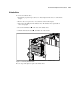
Table Of Contents
- Compaq ProLiant ML530 Servers Maintenance and Service Guide
- Notice Page
- Table of Contents
- About This Guide
- Chapter 1: Illustrated Parts List
- Chapter 2: Removal and Replacement Procedures
- Electrostatic Discharge Information
- Symbols on Equipment
- Preparation Procedures
- Tower Model Front Bezel Door
- Rack Mount Bezel
- Access Panel
- Fans
- Removable Media and Mass Storage Devices
- Cable Routing Diagrams
- System Board Tray
- System Board Components
- Hot Plug Power Supplies
- Power Backplane Board
- Power On/Standby Switch
- Chapter 3: Diagnostics and Troubleshooting
- Diagnostic Tools Utility Overview
- Default Configuration
- Utilities Access
- Power On Self Test
- Diagnostics Software
- Steps for Diagnostics
- 100–199, Primary Processor Test Error Codes
- 200–299, Memory Test Error Codes
- 300–399, Keyboard Test Error Codes
- 400–499, Parallel Printer Test Error Codes
- 500–599, Video Display Unit Test Error Codes
- 600–699, Diskette Drive Test Error Codes
- 800–899, Video Board Test Error Codes
- 1100–1199, Serial Test Error Codes
- 1200–1299, Modem Communications Test Error Codes
- 1700–1799, Hard Drive Test Error Codes
- 1900–1999, Tape Drive Test Error Codes
- 2400–2499, Advanced VGA Board Test Error Codes
- 6000–6099, Compaq NIC Boards Test Error Codes
- 6500–6599, SCSI Hard Drive Test Error Codes
- 6700–6799, SCSI Tape Drive Test Error Codes
- 8600–8699, Pointing Device Interface Test Error Codes
- Array Diagnostic Utility
- Integrated Management Log
- Rapid Error Recovery
- Remote Service Features
- ROMPaq Error Recovery Options
- Compaq Insight Manager
- Chapter 4: Connectors, Switches, Jumpers, and LED Indicators
- Chapter 5: Physical and Operating Specifications
- Index
Removal and Replacement Procedures 2-21
Hard Drive Cage with Backplane Board
CAUTION: If an active hard drive is replaced while the system is powered down, a POST error
message (1786) will occur when the system is powered up. The following prompt will appear:
PRESS <F1> TO BOOT THE SYSTEM AND REBUILD THE REPLACED DRIVE, OR
PRESS <F2> TO BOOT THE SYSTEM WITHOUT REBUILDING THE DRIVE(S).
Pressing F2 will cause permanent data loss to the logical hard drive. Press F2 only if all of the
hard drives were replaced or if complete data loss is desired.
To remove the hard drive cage with backplane board:
1. Perform the preparation procedures. See “Powering Down the Server” earlier in this
chapter.
2. Remove the front bezel and access panel.
■ For the tower model, see “Tower Model Front Bezel Door” and “Rack-Mount Bezel”
earlier in this chapter.
■ For the rack model, see “Rack-Mount Bezel” earlier in this chapter.
3. Remove all hard drives from the bays of the cage to be removed. See “Hot-Plug SCSI
Hard Drives” earlier in this chapter.
4. Remove the hard drive fan air baffle. See “Hard Drive Fan Air Baffle” earlier in this
chapter.
5. Disconnect all cabling. The SCSI A signal cable is color-coded blue, and the SCSI B
signal cable is color-coded yellow.