
ProLiant ML530 Servers Maintenance and Service Guide
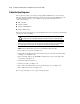


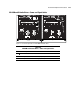


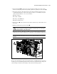


Table Of Contents
- Compaq ProLiant ML530 Servers Maintenance and Service Guide
- Notice Page
- Table of Contents
- About This Guide
- Chapter 1: Illustrated Parts List
- Chapter 2: Removal and Replacement Procedures
- Electrostatic Discharge Information
- Symbols on Equipment
- Preparation Procedures
- Tower Model Front Bezel Door
- Rack Mount Bezel
- Access Panel
- Fans
- Removable Media and Mass Storage Devices
- Cable Routing Diagrams
- System Board Tray
- System Board Components
- Hot Plug Power Supplies
- Power Backplane Board
- Power On/Standby Switch
- Chapter 3: Diagnostics and Troubleshooting
- Diagnostic Tools Utility Overview
- Default Configuration
- Utilities Access
- Power On Self Test
- Diagnostics Software
- Steps for Diagnostics
- 100–199, Primary Processor Test Error Codes
- 200–299, Memory Test Error Codes
- 300–399, Keyboard Test Error Codes
- 400–499, Parallel Printer Test Error Codes
- 500–599, Video Display Unit Test Error Codes
- 600–699, Diskette Drive Test Error Codes
- 800–899, Video Board Test Error Codes
- 1100–1199, Serial Test Error Codes
- 1200–1299, Modem Communications Test Error Codes
- 1700–1799, Hard Drive Test Error Codes
- 1900–1999, Tape Drive Test Error Codes
- 2400–2499, Advanced VGA Board Test Error Codes
- 6000–6099, Compaq NIC Boards Test Error Codes
- 6500–6599, SCSI Hard Drive Test Error Codes
- 6700–6799, SCSI Tape Drive Test Error Codes
- 8600–8699, Pointing Device Interface Test Error Codes
- Array Diagnostic Utility
- Integrated Management Log
- Rapid Error Recovery
- Remote Service Features
- ROMPaq Error Recovery Options
- Compaq Insight Manager
- Chapter 4: Connectors, Switches, Jumpers, and LED Indicators
- Chapter 5: Physical and Operating Specifications
- Index
2-26 Compaq ProLiant ML530 Servers Maintenance and Service Guide
Cable Routing Diagrams
The location and routing of each cable in Compaq ProLiant ML530 servers is shown in the
following diagrams. For further information, refer to the Compaq ProLiant ML530 Setup and
Installation Guide. To improve serviceability, the signal cables and system board are
color-coded as follows:
■ Blue = SCSI A
■ Yellow = SCSI B
■ Orange = CD-ROM drive
■ Purple = Diskette drive
When replacing the system board or power backplane board, remove the cables in the following
sequence for easier accessibility.
CAUTION: Due to the sliding design of the system board tray, the cables must be routed
properly. Cables can be damaged by pinching or chafing if not routed or contained properly.
IMPORTANT: Some cables are held to the side of the chassis with cable clips or are bound by straps
with hook-and-loop fasteners to keep the cables properly stored. The clips can be opened by releasing
the clip tab. Replace the cable in the clips or strap when completing cable routing procedures.
NOTE: Remove the PCI bracket for easier access. See “PCI Bracket” later in the chapter.
1. Power cables for system fans. See Figure 2-18.
2. Signal cables for SCSI hard drives and removable media devices (blue and yellow cables).
See Figure 2-19 and Figure 2-20.
3. Power and signal cables for the CD-ROM and diskette drives (orange and purple cables,
respectively). See Figure 2-21.
4. System data cable. See Figure 2-22.
5. System power cables. See Figure 2-23.
6. Power cables for SCSI hard drives and removable media devices. See Figure 2-24.
7. Power cables for drive fans. See Figure 2-25.
Reverse steps 1 through 7 to connect power and signal cables.