
ProLiant ML530 Servers Maintenance and Service Guide


Table Of Contents
- Compaq ProLiant ML530 Servers Maintenance and Service Guide
- Notice Page
- Table of Contents
- About This Guide
- Chapter 1: Illustrated Parts List
- Chapter 2: Removal and Replacement Procedures
- Electrostatic Discharge Information
- Symbols on Equipment
- Preparation Procedures
- Tower Model Front Bezel Door
- Rack Mount Bezel
- Access Panel
- Fans
- Removable Media and Mass Storage Devices
- Cable Routing Diagrams
- System Board Tray
- System Board Components
- Hot Plug Power Supplies
- Power Backplane Board
- Power On/Standby Switch
- Chapter 3: Diagnostics and Troubleshooting
- Diagnostic Tools Utility Overview
- Default Configuration
- Utilities Access
- Power On Self Test
- Diagnostics Software
- Steps for Diagnostics
- 100–199, Primary Processor Test Error Codes
- 200–299, Memory Test Error Codes
- 300–399, Keyboard Test Error Codes
- 400–499, Parallel Printer Test Error Codes
- 500–599, Video Display Unit Test Error Codes
- 600–699, Diskette Drive Test Error Codes
- 800–899, Video Board Test Error Codes
- 1100–1199, Serial Test Error Codes
- 1200–1299, Modem Communications Test Error Codes
- 1700–1799, Hard Drive Test Error Codes
- 1900–1999, Tape Drive Test Error Codes
- 2400–2499, Advanced VGA Board Test Error Codes
- 6000–6099, Compaq NIC Boards Test Error Codes
- 6500–6599, SCSI Hard Drive Test Error Codes
- 6700–6799, SCSI Tape Drive Test Error Codes
- 8600–8699, Pointing Device Interface Test Error Codes
- Array Diagnostic Utility
- Integrated Management Log
- Rapid Error Recovery
- Remote Service Features
- ROMPaq Error Recovery Options
- Compaq Insight Manager
- Chapter 4: Connectors, Switches, Jumpers, and LED Indicators
- Chapter 5: Physical and Operating Specifications
- Index
Removal and Replacement Procedures 2-33
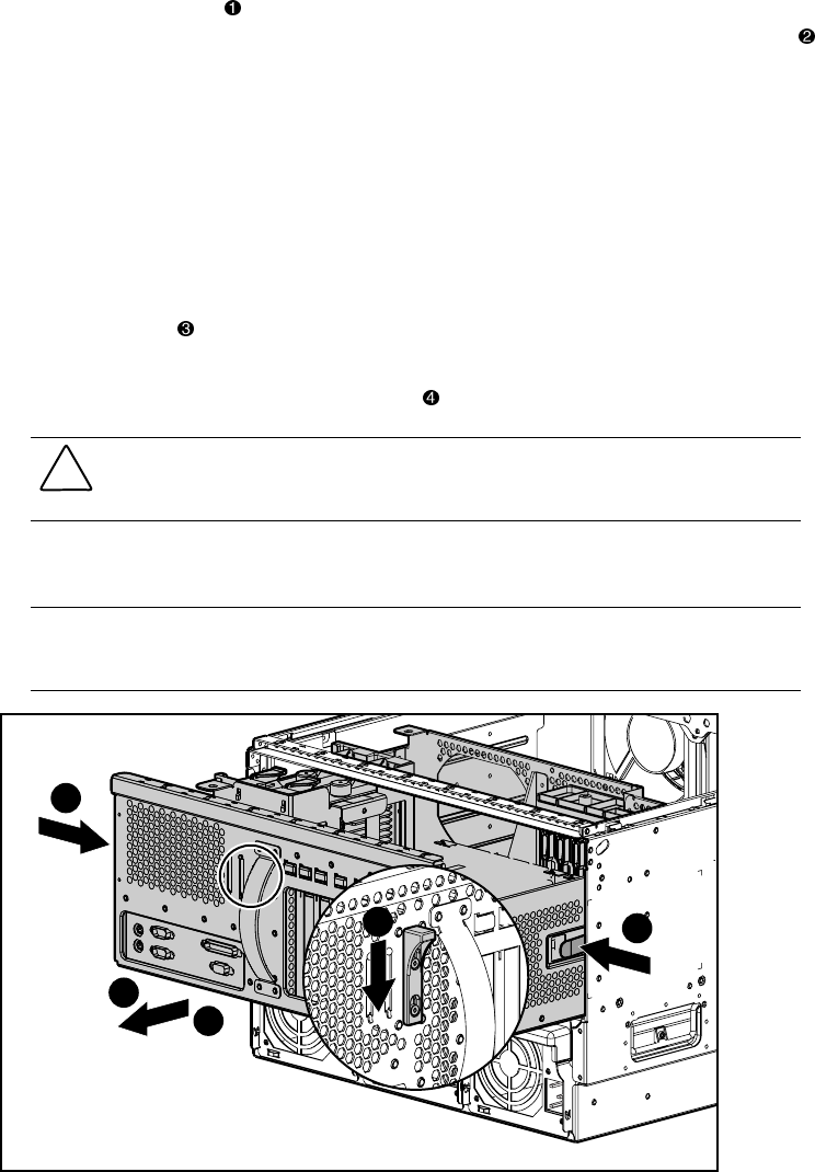
4. Press the thumb latch adjacent to the system board tray handle to release the system
board tray. Using the system board tray handle, pull the tray partially out of the chassis
.
5. Disconnect and remove all cables from the system board and PCI expansion board. See
“Cable Routing Diagrams” earlier in this chapter. To improve serviceability, the signal
cables and system board are color-coded as follows:
■ Blue = SCSI A
■ Yellow = SCSI B
■ Orange = CD-ROM drive
■ Purple = Diskette drive
6. Push the latches on the system board tray slides to allow the tray to slide further out of
the chassis.
7. Pull the system board tray out of the chassis .
CAUTION: Electrostatic discharge can damage electronic components. Be sure you are
properly grounded before beginning any installation or removal procedure. See “Electrostatic
Discharge Information” earlier in this chapter.
8. Disconnect and remove all memory modules, processors, PCI expansion boards, and
cables from the system board. Place these components on a nonconductive work surface.
IMPORTANT: Options must be reinstalled in the same position from where they were removed. See
replacement procedures in this chapter for each of the options requiring installation on the new system
board tray.
3
2
3
1
4
Figure 2-26. Removing the system board tray
Reverse steps 1 through 8 to replace the system board tray, reinstalling all removed memory
modules, processors, and PCI expansion boards onto the new system board tray. Change the
switch settings to match the switch settings on the system board being replaced.