
ProLiant ML530 Servers Maintenance and Service Guide


Table Of Contents
- Compaq ProLiant ML530 Servers Maintenance and Service Guide
- Notice Page
- Table of Contents
- About This Guide
- Chapter 1: Illustrated Parts List
- Chapter 2: Removal and Replacement Procedures
- Electrostatic Discharge Information
- Symbols on Equipment
- Preparation Procedures
- Tower Model Front Bezel Door
- Rack Mount Bezel
- Access Panel
- Fans
- Removable Media and Mass Storage Devices
- Cable Routing Diagrams
- System Board Tray
- System Board Components
- Hot Plug Power Supplies
- Power Backplane Board
- Power On/Standby Switch
- Chapter 3: Diagnostics and Troubleshooting
- Diagnostic Tools Utility Overview
- Default Configuration
- Utilities Access
- Power On Self Test
- Diagnostics Software
- Steps for Diagnostics
- 100–199, Primary Processor Test Error Codes
- 200–299, Memory Test Error Codes
- 300–399, Keyboard Test Error Codes
- 400–499, Parallel Printer Test Error Codes
- 500–599, Video Display Unit Test Error Codes
- 600–699, Diskette Drive Test Error Codes
- 800–899, Video Board Test Error Codes
- 1100–1199, Serial Test Error Codes
- 1200–1299, Modem Communications Test Error Codes
- 1700–1799, Hard Drive Test Error Codes
- 1900–1999, Tape Drive Test Error Codes
- 2400–2499, Advanced VGA Board Test Error Codes
- 6000–6099, Compaq NIC Boards Test Error Codes
- 6500–6599, SCSI Hard Drive Test Error Codes
- 6700–6799, SCSI Tape Drive Test Error Codes
- 8600–8699, Pointing Device Interface Test Error Codes
- Array Diagnostic Utility
- Integrated Management Log
- Rapid Error Recovery
- Remote Service Features
- ROMPaq Error Recovery Options
- Compaq Insight Manager
- Chapter 4: Connectors, Switches, Jumpers, and LED Indicators
- Chapter 5: Physical and Operating Specifications
- Index
2-34 Compaq ProLiant ML530 Servers Maintenance and Service Guide
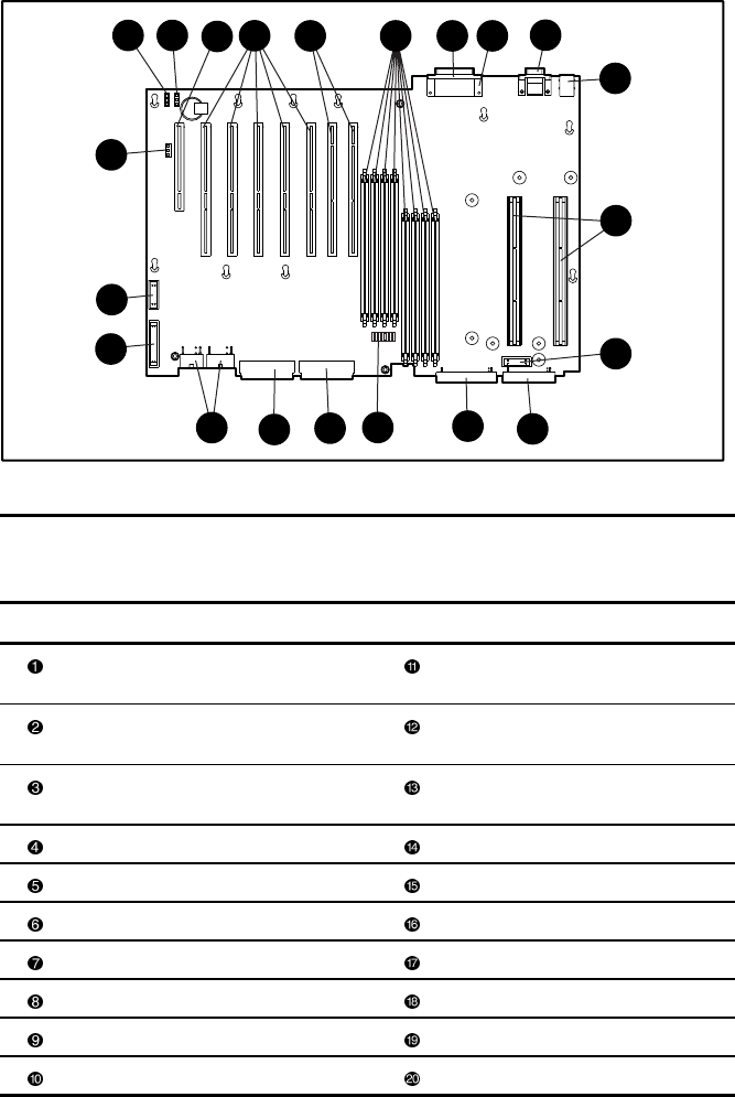
System Board Components
The system board is mounted to the inside of the tray. When the access panel and the CPU fan
air baffle are removed, all the system board components are visible.
1
6
5
4
14
15
16
3
7
8
9
12
11
10
17
10
2
18
13
19
20
Figure 2-27. System board components
Table 2-7
System Board Components
Item Description Item Description
32-bit, 33-MHz primary PCI bus Diskette drive signal cable
connector (purple)
64-bit, 33-MHz, tertiary PCI bus IDE CD-ROM signal cable
connector (orange)
64-bit, 66-MHz, 3-volt only
secondary PCI bus
Configuration switch
2 sets of 4 DIMM memory sockets SCSI channel A connector (blue)
Parallel port SCSI channel B connector (yellow)
Video port Power connectors
Serial ports System data connector
Keyboard/mouse interface Remote power switch header
Processor slots Battery power header
Fan cable connectors (2 locations) External battery header