
ProLiant ML530 Servers Maintenance and Service Guide

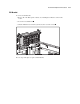
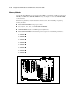


Table Of Contents
- Compaq ProLiant ML530 Servers Maintenance and Service Guide
- Notice Page
- Table of Contents
- About This Guide
- Chapter 1: Illustrated Parts List
- Chapter 2: Removal and Replacement Procedures
- Electrostatic Discharge Information
- Symbols on Equipment
- Preparation Procedures
- Tower Model Front Bezel Door
- Rack Mount Bezel
- Access Panel
- Fans
- Removable Media and Mass Storage Devices
- Cable Routing Diagrams
- System Board Tray
- System Board Components
- Hot Plug Power Supplies
- Power Backplane Board
- Power On/Standby Switch
- Chapter 3: Diagnostics and Troubleshooting
- Diagnostic Tools Utility Overview
- Default Configuration
- Utilities Access
- Power On Self Test
- Diagnostics Software
- Steps for Diagnostics
- 100–199, Primary Processor Test Error Codes
- 200–299, Memory Test Error Codes
- 300–399, Keyboard Test Error Codes
- 400–499, Parallel Printer Test Error Codes
- 500–599, Video Display Unit Test Error Codes
- 600–699, Diskette Drive Test Error Codes
- 800–899, Video Board Test Error Codes
- 1100–1199, Serial Test Error Codes
- 1200–1299, Modem Communications Test Error Codes
- 1700–1799, Hard Drive Test Error Codes
- 1900–1999, Tape Drive Test Error Codes
- 2400–2499, Advanced VGA Board Test Error Codes
- 6000–6099, Compaq NIC Boards Test Error Codes
- 6500–6599, SCSI Hard Drive Test Error Codes
- 6700–6799, SCSI Tape Drive Test Error Codes
- 8600–8699, Pointing Device Interface Test Error Codes
- Array Diagnostic Utility
- Integrated Management Log
- Rapid Error Recovery
- Remote Service Features
- ROMPaq Error Recovery Options
- Compaq Insight Manager
- Chapter 4: Connectors, Switches, Jumpers, and LED Indicators
- Chapter 5: Physical and Operating Specifications
- Index
Removal and Replacement Procedures 2-43
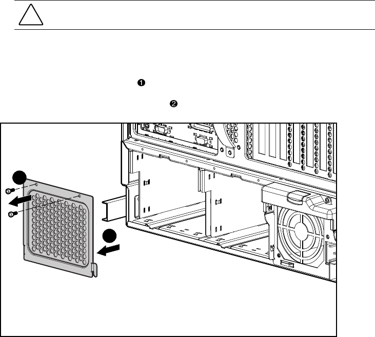
Power Supply Blanking Panel
CAUTION: When the power supply is not being replaced, cover the opening with a
power supply blanking panel to maintain proper airflow.
To remove a power supply blanking panel:
1. Perform the preparation procedures. See “Hot-Pluggable Device” earlier in this chapter.
2. Remove the two T-15 screws securing the power supply blanking panel to the chassis.
3. Pull the power supply blanking panel away from the chassis.
1
2
Figure 2-36. Removing the power supply blanking panel
Reverse steps 1 through 3 to replace a power supply blanking panel.