
ProLiant ML530 Servers Maintenance and Service Guide

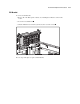


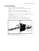
Table Of Contents
- Compaq ProLiant ML530 Servers Maintenance and Service Guide
- Notice Page
- Table of Contents
- About This Guide
- Chapter 1: Illustrated Parts List
- Chapter 2: Removal and Replacement Procedures
- Electrostatic Discharge Information
- Symbols on Equipment
- Preparation Procedures
- Tower Model Front Bezel Door
- Rack Mount Bezel
- Access Panel
- Fans
- Removable Media and Mass Storage Devices
- Cable Routing Diagrams
- System Board Tray
- System Board Components
- Hot Plug Power Supplies
- Power Backplane Board
- Power On/Standby Switch
- Chapter 3: Diagnostics and Troubleshooting
- Diagnostic Tools Utility Overview
- Default Configuration
- Utilities Access
- Power On Self Test
- Diagnostics Software
- Steps for Diagnostics
- 100–199, Primary Processor Test Error Codes
- 200–299, Memory Test Error Codes
- 300–399, Keyboard Test Error Codes
- 400–499, Parallel Printer Test Error Codes
- 500–599, Video Display Unit Test Error Codes
- 600–699, Diskette Drive Test Error Codes
- 800–899, Video Board Test Error Codes
- 1100–1199, Serial Test Error Codes
- 1200–1299, Modem Communications Test Error Codes
- 1700–1799, Hard Drive Test Error Codes
- 1900–1999, Tape Drive Test Error Codes
- 2400–2499, Advanced VGA Board Test Error Codes
- 6000–6099, Compaq NIC Boards Test Error Codes
- 6500–6599, SCSI Hard Drive Test Error Codes
- 6700–6799, SCSI Tape Drive Test Error Codes
- 8600–8699, Pointing Device Interface Test Error Codes
- Array Diagnostic Utility
- Integrated Management Log
- Rapid Error Recovery
- Remote Service Features
- ROMPaq Error Recovery Options
- Compaq Insight Manager
- Chapter 4: Connectors, Switches, Jumpers, and LED Indicators
- Chapter 5: Physical and Operating Specifications
- Index
Removal and Replacement Procedures 2-45
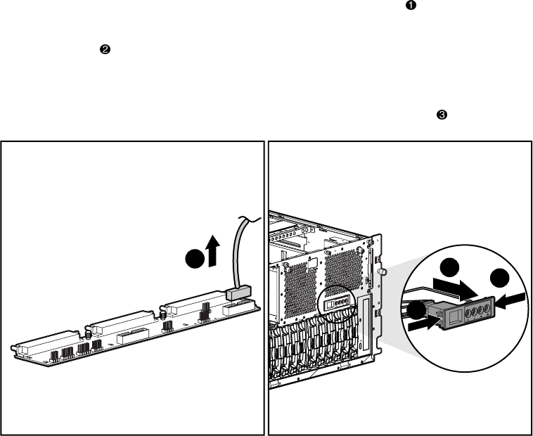
Power On/Standby Switch
To remove the Power On/Standby switch and cable assembly:
1. Perform the preparation procedures. See “Powering Down the Server” earlier in this
chapter.
2. Remove the access panel. See “Access Panel” earlier in this chapter.
3. Remove the hard drive fan air baffle. See “Hard Drive Fan Air Baffle” earlier in this
chapter.
4. Disconnect the power switch cable from the power backplane board , and feed it through
the cable grommet.
5. Press the tabs on both sides of the switch to release it.
NOTE: A 4-mm flat-blade screwdriver can be used to assist with pressing the tabs.
6. With the tabs released, pull the switch and cable out the front of the bezel .
2
1
2
3
Figure 2-38. Removing the Power On/Standby switch
Reverse steps 1 through 6 to replace the Power On/Standby switch.