HP ProLiant ML570 Generation 3 Server User Guide February 2006 (Fourth Edition) Part Number 374178-004
© Copyright 2004, 2006 Hewlett-Packard Development Company, L.P. The information contained herein is subject to change without notice. The only warranties for HP products and services are set forth in the express warranty statements accompanying such products and services. Nothing herein should be construed as constituting an additional warranty. HP shall not be liable for technical or editorial errors or omissions contained herein. Microsoft, Windows, and Windows NT are U.S.
Contents Server component identification...................................................................................................... 7 Front panel components (SCSI).................................................................................................................... 7 Front panel components (SAS) .................................................................................................................... 8 Front panel LEDs and buttons ..........................................
Hot-plug SCSI hard drive options............................................................................................................... 44 Installing hot-plug SCSI hard drives .................................................................................................. 44 Hot-plug SAS hard drive options ............................................................................................................... 45 Installing a hot-plug SAS hard drive ..........................................
ROMPaq utility.............................................................................................................................. 89 Integrated Lights-Out technology ...................................................................................................... 89 StorageWorks library and tape tools................................................................................................ 89 HP Systems Insight Manager ...................................................................
Modifications........................................................................................................................................ 115 Cables ................................................................................................................................................. 115 Mouse compliance statement .................................................................................................................. 115 Canadian notice (Avis Canadien)........................
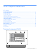
Server component identification In this section Front panel components (SCSI) .................................................................................................................. 7 Front panel components (SAS) ................................................................................................................... 8 Front panel LEDs and buttons .....................................................................................................................
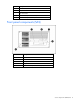
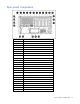
Item Description 2 DVD-ROM drive 3 USB port 4 Tape drive blank 5 SCSI channel 2 (channels 0 and 1) 6 SCSI channel 1 (channels 0-7) Front panel components (SAS) Item Description 1 Diskette drive blank 2 DVD-ROM drive 3 USB port 4 Tape drive blank 5 SAS hard drives (SAS IDs 1 through 18) Server component identification 8
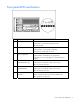
Front panel LEDs and buttons Item Description Status 1 UID switch and LED Blue = Activated Flashing blue = System being managed remotely Off = Deactivated 2 Internal system health LED Green = Normal (system on) Flashing Amber = System health is degraded Flashing Red = System health is critical 3 External system health (power supply) LED Green = Normal (system on) Flashing Amber = Redundant power supply failure Flashing Red = Power supply failure. No operational power supplies.
Rear panel components Item Description 1 NIC 2 2 NIC 1 3 USB Ports 4 iLO 5 Parallel port 6 64-bit/100-MHz PCI-X slot 1 7 64-bit/100-MHz PCI-X slot 2 8 64-bit/100-MHz PCI-X slot 3 9 64-bit/100-MHz PCI-X slot 4 10 PCI Express x4 slot 5 11 PCI Express x4 slot 6 12 PCI Express x4 slot 7 13 PCI Express x4 slot 8 14 64-bit/133-MHz PCI-X hot-plug slot 9 15 64-bit/133-MHz PCI-X hot-plug slot 10 16 Power supply (primary) 17 Power supply blank 18 T-15 Torx screwdriver 19 Extern
Rear panel LEDs and buttons Item Description LED color Status 1 Unit ID LED Blue On = Activated Flashing = System remotely managed Off = Deactivated 2 3 4 NIC Activity LED (Integrated NC7782) Green NIC Link LED (Integrated NC7782) Green iLO NIC Activity LED Green On or flashing = Linked to network Off = Not linked to network On = Network activity Off = No network activity On or flashing = Network activity Off = No network activity 5 iLO NIC Link LED Green On = Linked to network Off = Not
System board components Item Description 1 64-bit/133-MHz PCI-X Hot-Plug slot 10 2 64-bit/133-MHz PCI-X Hot-Plug slot 9 3 PCI Express x4 slot 8 4 PCI Express x4 slot 7 5 PCI Express x4 slot 6 6 PCI Express x4 slot 5 7 64-bit/100-MHz PCI-X slot 4 8 64-bit/100-MHz PCI-X slot 3 9 64-bit/100-MHz PCI-X slot 2 10 64-bit/100-MHz PCI-X slot 1 11 Memory board slot 1 12 Memory board slot 2 13 Memory board slot 3 14 Memory board slot 4 15 PPM slot 1 16 PPM slot 2 17 QuickFind diagno
Item Description 26 Fan board signal connector 27 Fan board power connector 28 Processor socket 1 29 Power connector 30 RILOE II connector 31 Power connector 32 Fan connector 33 Fan connector 34 Power supply signal connector 35 USB option connector 36 SCSI connector 2 37 SCSI connector 1 38 PCI hot-plug board connector System maintenance switches The system maintenance switch (SW1) is an eight-position switch that is reserved. The default position for all eight positions is Off.
Position Description Function S6 Invalid configuration Off = Normal S7 Reserved S8 Reserved On = ROM treats system configuration as invalid When the system maintenance switch position 6 is set to the On position, the system is prepared to erase all system configuration settings from both CMOS and NVRAM. CAUTION: Clearing CMOS and/or NVRAM deletes configuration information. Be sure to properly configure the server or data loss could occur.
System LED and color Internal health LED color Status System temperature alert (amber) Flashing red System temperature has exceeded OS cautionary level or critical hardware level. Fan (amber) Flashing red A required fan has failed. Fan (amber) Flashing amber A redundant fan has failed. System board LEDs and QuickFind Diagnostic display codes In normal operations, all the LEDs are off unless one of the components fails. When a component fails, the LED illuminates amber.
Code Component Explanation t4 Processor 4 unsupported Processor 4 unsupported. Replace with a supported processor. P1 Processor 1 is missing Processor 1 is missing, and is required to boot. Install Processor 1. If processor 4 is installed and the system is booting up, the P1 code and Port 84/85 will be displayed for 1 second each to show the unit is booting. U1 PPM1 is missing Processor 1 is installed without PPM 1. Install PPM 1. U2 PPM2 is missing Processor 2 is installed without PPM 2.
SATA or SAS hard drive LEDs Item LED description Status 1 Fault/UID status Amber = Drive failure Flashing amber = Fault-process activity Blue = Unit identification is active Off = No fault-process activity 2 Online/Activity status Green = Drive activity Flashing green = High activity on the drive or drive is being configured as part of an array Off = No drive activity SAS and SATA hard drive LED combinations Online/activity LED (green) Fault/UID LED (amber/blue) On, off, or flashing Alternating
Online/activity LED (green) Fault/UID LED (amber/blue) Flashing regularly Off (1 Hz) Interpretation Do not remove the drive. Removing a drive may terminate the current operation and cause data loss. The drive is rebuilding, or it is part of an array that is undergoing capacity expansion or stripe migration. Flashing irregularly Amber, flashing regularly (1 Hz) The drive is active, but a predictive failure alert has been received for this drive. Replace the drive as soon as possible.
Hot-plug SCSI hard drive LEDs Item LED Description Status 1 Activity status On = Drive activity Flashing = High activity on the drive or drive is being configured as part of an array. Off = No drive activity 2 On = Drive is part of an array and is currently working. Online status Flashing = Either (1) the drive is part of an array being selected by an array configuration utility; (2) Drive Identification has been selected in HP SIM; or (3) drive firmware is being updated. Off = Drive is offline.
Activity LED (1) Online LED Fault LED (2) (3) Interpretation On or flashing Flashing Do not remove the drive. Removing a drive may terminate the current operation and cause data loss. Off The drive is rebuilding or undergoing capacity expansion. On Off Off Do not remove the drive. The drive is being accessed, but (1) it is not configured as part of an array; (2) it is a replacement drive and rebuild has not yet started; or (3) it is spinning up during the POST sequence.
If removal of a single memory board is required and it is the only memory board, power down the server and make the necessary memory changes.
Item Description Status 9 DIMM 5 LED Green = DIMM installed Amber = Failed or degraded DIMM Flashing amber = DIMM configuration error Off = No DIMM installed 10 DIMM 6 LED Green = DIMM installed Amber = Failed or degraded DIMM Flashing amber = DIMM configuration error Off = No DIMM installed 11 Online Spare LED Green = Online spare mode Amber = Degraded online spare mode Flashing amber = Invalid AMP mode* Off = Not in Online Spare mode Hot-Plug Mirrored LED 12 Green = Mirrored mode Amber = Deg
LED Advanced ECC Memory Online Spare Memory Hot-Plug Mirrored Memory Hot-Plug RAID Memory DIMM 1 to 6, if populated Green Green Green Green Online Spare status Off Green Off Off Mirrored status Off Off Green Off RAID status Off Off Off Green Board Removable Off Off Green Green DIMM slot locations DIMM slot Description Bank 1 PC2-3200R DIMM slot Bank A 2 PC2-3200R DIMM slot Bank A 3 PC2-3200R DIMM slot Bank B 4 PC2-3200R DIMM slot Bank B 5 PC2-3200R DIMM slot Ba
Hot-plug power supply LEDs Item Description 1 Primary power supply power LED (green) 2 Primary power supply fail LED (amber) 3 Redundant power supply power LED (green) 4 Redundant power supply fail LED (amber) Power supply condition Power LED (green) Fail LED (amber) No AC power to all power supply units Off Off No AC power to this power supply unit only or power supply failure (includes over voltage and over temperature) Off On AC present/Standby outputs on Flashing Off Power supply
Fan locations Item Description Configuration 1 Fan 1 Redundant 2 Fan 2 Primary 3 Fan 3 Redundant 4 Fan 4 Primary 5 Fan 5 Redundant 6 Fan 6 Primary Hot-plug fan LEDs Server component identification 25
Status Green = Operating normally Amber = Failed Off = No power Server component identification 26
Server operations In this section Power up the server ................................................................................................................................ 27 Power down the server............................................................................................................................ 27 Extending the server from the rack............................................................................................................
2. Extend the server on the rack rails until the server rail-release latches engage. WARNING: To reduce the risk of personal injury or equipment damage, be sure that the rack is adequately stabilized before extending a component from the rack. WARNING: To reduce the risk of personal injury, be careful when pressing the server rail-release latches and sliding the server into the rack. The sliding rails could pinch your fingers. 3.
Unlocking and removing the tower bezel Tower servers have a bezel that must be unlocked and opened before accessing the hard drive cage, diskette drive, DVD drive, and the power switch. In addition, the bezel is also removable when converting from a tower server to a rack server. To unlock the tower bezel, use the key provided with the server to unlock the bezel with a counterclockwise turn.
If necessary, remove the tower bezel. Removing the rack bezel The rack bezel must remain installed during normal server operations. The rack bezel remains installed for all hardware options installations, except for the following situations: • Removing or replace a SCSI hard drive cage • Removing or replacing a SAS hard drive cage • Converting the server from a rack model to a tower model To remove the rack bezel: 1.
5. Release the snap at the base of the rack bezel and remove the rack bezel. Access panel WARNING: To reduce the risk of personal injury from hot surfaces, allow the drives and the internal system components to cool before touching them. CAUTION: Do not operate the server for long periods with the access panel open or removed. Operating the server in this manner results in improper airflow and improper cooling that can lead to thermal damage. 1.
Server setup In this section Optional installation services ................................................................................................................... 32 Rack planning resources ......................................................................................................................... 33 Optimum environment............................................................................................................................. 33 Rack warnings and cautions .........
For more information on Care Packs, refer to the HP website (http://www.hp.com/hps/carepack/servers/cp_proliant.html). Rack planning resources The rack resource kit ships with all HP branded or Compaq branded 9000, 10000, and H9 series racks. For more information on the content of each resource, refer to the rack resource kit documentation. If you intend to deploy and configure multiple servers in a single rack, refer to the white paper on highdensity deployment at the HP website (http://www.hp.
CAUTION: If a third-party rack is used, observe the following additional requirements to ensure adequate airflow and to prevent damage to the equipment: • Front and rear doors—If the 42U rack includes closing front and rear doors, you must allow 5,350 sq cm (830 sq in) of holes evenly distributed from top to bottom to permit adequate airflow (equivalent to the required 64 percent open area for ventilation).
Furthermore, you must be sure that all power distribution devices used in the installation, such as branch wiring and receptacles, are listed or certified grounding-type devices. Because of the high ground-leakage currents associated with multiple servers connected to the same power source, HP recommends the use of a PDU that is either permanently wired to the building’s branch circuit or includes a nondetachable cord that is wired to an industrial-style plug.
CAUTION: Do not operate the server for long periods with the access panel open or removed. Operating the server in this manner results in improper airflow and improper cooling that can lead to thermal damage. Identifying rack server shipping carton contents Unpack the server shipping carton and locate the materials and documentation necessary for installing the server. All the rack mounting hardware necessary for installing the server into the rack is included with the rack or the server.
Setting up a tower server Follow these steps to set up a tower model server. If you are going to install the server into a rack, refer to the rack installation section ("Installing the server into the rack" on page 37). 1. Connect peripheral devices to the server. WARNING: To reduce the risk of electric shock, fire, or damage to the equipment, do not plug telephone or telecommunications connectors into RJ-45 connectors.
Powering up and configuring the server To power up the server, press the Power On/Standby button. While the server boots, RBSU is automatically configured to prepare the server for operating system installation. To manually configure the utilities, press the F9 key when prompted during the boot process to change the server settings using RBSU. The system is set up by default for the English language.
Hardware options installation In this section Preparing the server for options installation ............................................................................................... 39 Processor options ................................................................................................................................... 39 Hot-plug SCSI hard drive options .............................................................................................................
CAUTION: To prevent possible server malfunction, do not mix processors of different speeds or cache sizes. Refer to the label on the processor heatsink for a description of the processor. IMPORTANT: Populate the processors in the following order: 1, 2, 4, 3. IMPORTANT: If upgrading processor speed or adding additional processors, update the system ROM before installing the processor. IMPORTANT: Processor socket 1 and PPM slot 1 must be populated at all times or the server does not function properly.
5. Unlock the processor retaining bracket. 6. Open the processor retaining bracket. 7. Open the processor locking lever. CAUTION: Failure to completely open the processor locking lever prevents the processor from seating during installation, leading to hardware damage. 8. Install the processor assembly into the processor socket.
IMPORTANT: Determine the correct processor orientation by observing the guide pins on the base of the processor retaining bracket and the three corresponding guide slots on the processor assembly. 9. Close the processor locking lever. CAUTION: To prevent possible server malfunction or damage to the equipment, be sure to completely close the processor locking lever.
10. Close and lock the processor retaining bracket. 11. Open the latches on the PPM retaining bracket and remove the PPM retaining bracket. 12. Install the PPM.
IMPORTANT: Always install a PPM when you install a processor. The system fails to boot if the corresponding PPM is missing. NOTE: The appearance of compatible PPMs may vary. 13. Reinstall the PPM retaining bracket. 14. Reinstall the processor air baffle. 15. Reinstall the access panel ("Access panel" on page 31).
1. Remove the hard drive blank. 2. Install the hard drive. 3. Determine the status of the hard drive from the hot-plug hard drive LEDs ("SATA or SAS hard drive LEDs" on page 17). 4. Resume normal server operations. Hot-plug SAS hard drive options When adding hard drives to the server, observe the following general guidelines: • The system automatically sets all device numbers.
Installing a hot-plug SAS hard drive 1. Remove the SAS hard drive blank. 2. Prepare the SAS hard drive.
3. Install the hard drive. 4. Determine the status of the hard drive from the hot-plug SAS hard drive LED combinations ("SAS and SATA hard drive LED combinations" on page 17). Redundant hot-plug fans The server supports redundant hot-plug fans to provide proper airflow to the system if a primary fan fails. In the standard configuration, primary fans 2, 4, and 6 cool the server. For the redundant configuration, fans 1, 3, and 5 are added to back up the primary fans.
NOTE: Any hot-plug fan provided in the redundant hot-plug fan cage option kit can be installed in any of the hot-plug fan slots. Fans are keyed to fit only one way in the slot. 4. Observe the LED on each installed fan to be sure it is green. 5. Observe the internal system health LED on the front panel to be sure it is green ("Front panel LEDs and buttons" on page 9).
3. Remove the malfunctioning hot-plug fan. 4. Install a new hot-plug fan ("Installing hot-plug fans" on page 47). 5. Replace additional fans if needed. 6. Observe the internal system health LED on the front panel and the LEDs on each installed fan to be sure it is green. NOTE: If the front panel internal system health LED is not green after you install hot-plug fans, reseat the hotplug fan or refer to the troubleshooting section. 7. Reinstall the access panel ("Access panel" on page 31).
1. Remove the power supply blank in the secondary hot-plug power supply bay. 2. Install the second hot-plug power supply. 3. Connect the power cord to the redundant power supply. 4. Secure the power cords to the retaining clip ("Setting up a tower server" on page 37). 5. Connect the power cord to the power source. 6. Be sure that the power supply LED is green. 7. Be sure that the front panel external health LED is green ("Front panel LEDs and buttons" on page 9).
Expansion boards The server supports PCI-X, PCI Express, and hot-plug PCI-X expansion boards. For location, refer to Rear Panel Components (on page 10).
Installing expansion boards CAUTION: To prevent damage to the server or expansion boards, do not remove or install expansion boards that are not hot-pluggable before powering down the server and disconnecting all AC power cords. 1. Remove the expansion slot cover ("Removing an expansion slot cover" on page 51). 2. Push back the retaining clip. 3. Install the expansion board. 4. Lock the PCI slot release lever and release the retaining clip if it does not automatically close and lock. 5.
RILOE II board The server comes with iLO remote management capability embedded on the system board. The 30-pin remote management connector for the RILOE II board is provided to reduce external cabling. The 30-pin connector provides power, keyboard, mouse, and other peripheral signals directly to the system board; therefore, the external AC power adapter and keyboard/mouse loopback cable are not needed for normal operations. The RILOE II board provides remote server manageability for ProLiant servers.
CAUTION: Always populate each media bay with either a device or a blank. Proper airflow can only be maintained when the bays are populated. Unpopulated drive bays can lead to improper cooling and thermal damage. To install an optional drive: 1. Power down the server (on page 27). 2. Use a T-15 Torx screwdriver to eject the drive blank, and pull the drive blank out of the chassis. 3. Install the optional drive into the server.
Removing the tape drive blank 1. Unlock and open the tower bezel ("Unlocking and removing the tower bezel" on page 29) (tower servers only). CAUTION: Always populate each media bay with either a device or a blank. Proper airflow can only be maintained when the bays are populated. Unpopulated drive bays can lead to improper cooling and thermal damage. 2. Pull the tape drive blank out of the chassis. 3. Store the blank for later use.
8. Remove the center wall. 9. Remove the memory cage. 10. Disconnect all required cables from the system board.
11. Remove the system board. 12. Remove the tape drive blank ("Removing the tape drive blank" on page 55). NOTE: Most devices have holes designed to correspond with the wire retainers that are installed in the upper slot of the guide clips. For devices that have holes designed to correspond to the lower slot of the guide clip, the wire retainer must be removed and reinstalled in the lower slot of the clip. If the device has holes that correspond to the upper slot, proceed to step 14.
d. Repeat for the right plastic clip. 15. Connect the power cable from the server to the tape drive. 16. Connect one end of the data cable to the tape drive and thread the other end into the server through the tape drive bay. IMPORTANT: Each SCSI device in the server must have a unique address. The server automatically sets all SCSI IDs for hot-plug drives, but you must set the SCSI IDs for devices installed in the media cage. 17. Slide the tape drive into the bay until it is seated securely. 18.
• Standard SCSI tape drive cabling • SCSI tape drive cabling to an expansion board 19. Reinstall the system board. 20. Reinstall the memory cage. 21. Reinstall the memory boards. 22. Reinstall any expansion boards. 23. Reinstall the center wall. 24. Reinstall the processor air baffle ("Processor options" on page 39). 25. Reinstall the access panel ("Access panel" on page 31). 26. Close the tower bezel (tower servers only) ("Unlocking and removing the tower bezel" on page 29). 27.
Memory options This server supports up to four memory boards. Each memory board contains six DIMM slots for a total of 24 DIMM slots in the server. Memory can be expanded by installing PC2-3200R Registered DDR2 DRAM DIMMs.
Configuration Bank A Bank B 7 Dual Dual Bank C • The system can be configured for any AMP mode in RBSU. RBSU displays a warning message if the selected AMP mode is not supported by the current configuration. However, if the DIMM configuration at POST does not meet the requirements for the AMP mode selected in RBSU, the server defaults to Advanced ECC. The system indicates this by displaying a message during POST and the status LED for the configured AMP mode flashes amber.
• • Multiple hot-add board insertions can be performed on the same server. For example, if a server has three empty memory board slots, three hot-add board insertions can be performed. • If multiple hot-add operations are performed, allow one board insertion operation to complete (as indicated by the memory board LEDs and OS logs) before inserting another memory board. If a memory board (which contains DIMMs) is unlocked while in Advanced ECC mode, audio alarms and visual alerts occur.
• If a mixture of single- and dual-rank DIMMs are used on a memory board, the dual-rank DIMMs should be two times the size of any single-rank DIMM. After installing DIMMs, use RBSU to configure the system for online spare memory support. Hot-plug mirrored memory Hot-Plug mirrored memory (mirrored memory) provides a higher level of memory protection than either Advanced ECC or Online Spare Memory.
• If you remove a board while the server is running and do not replace the board, the next reboot results in the system defaulting to Advanced ECC and Advanced ECC guidelines apply. Hot-plug RAID memory Hot-plug RAID memory (RAID memory) provides a similar level of memory protection as mirrored memory but obtains this protection using less total memory. For example, in a RAID memory configuration, 25% of the installed memory is not available to the OS.
3. Reinstall the memory board in the slot from which it was removed. The replacement procedures in this section apply to both hot-plug and non-hot-plug memory procedures, except as noted. IMPORTANT: Be sure to power down the server when performing board removal procedures in a server that is not configured for Mirrored or Hot-Plug RAID Memory. Observe the following warnings when performing a hot-plug replacement procedure.
NOTE: While the memory board with the failed or degraded DIMM is being removed, the system continues to read and write from the operational memory board(s). 7. Remove or install the DIMM. 8. Align the memory board with the memory slot and memory board guide clips. 9. Install the memory board into the server and close the ejector lever.
10. Move the locking switch to the locked position. NOTE: In hot-plug procedures, all LEDs now turn off except the board status LED, which flashes green while the board is rebuilding. This process may take several minutes. 11. Observe the LEDs on the top of the memory board to be sure that the memory is functioning properly ("Memory board LEDs and components" on page 20). The LED states will be valid when the memory board has finished rebuilding. 12. Replace the access panel ("Access panel" on page 31).
7. Remove the memory board and place on a flat surface.
8. Remove or install the DIMM. 9. Align the memory board with the memory slot and the memory board guide clips. 10. Install the memory board into the server and close the ejector lever.
11. Move the locking switch to the locked position. 12. Configure the memory ("Configuring the memory" on page 70). 13. Replace the access panel ("Access panel" on page 31). 14. Reinstall the server into the rack (rack servers only) ("Installing the server into the rack" on page 37). Configuring the memory Configuring the memory system of the server requires configuring both hardware and software. To configure the memory: 1. Install the correct amount of memory for the desired AMP mode.
ROM-based diagnostics 1. Power up the server (on page 27). 2. Press the F10 key, when prompted, to enter the System Maintenance menu. 3. Select Diagnostics. 4. Run the Memory Diagnostics. 5. After the memory has been tested, exit the utility and reboot. 6. Select the AMP mode ("Selecting the AMP mode" on page 71). Selecting the AMP mode 1. Upon reboot, press the F9 key, when prompted, to enter RBSU. 2. Select System Options. 3. Select Advanced Memory Protection. 4.
3. Remove all remaining external cables from the rear panel of the server, including any cables extending from external connectors on expansion boards. 4. Remove all hot-plug power supplies ("Redundant hot-plug power supply" on page 49). 5. Remove all hot-plug SCSI hard drives. 6. Remove the tower bezel ("Removing the tape drive blank" on page 55, "Unlocking and removing the tower bezel" on page 29). Removing the casters WARNING: The server is very heavy, up to 63.5 kg (140 lb).
2. Slide the tower cover toward the rear of the server and pull the cover away from the chassis. 3. Turn the server over 180 degrees so that the access panel is on top. Installing the rack bezel 1. Remove the access panel ("Access panel" on page 31). 2. Remove the tower bezel retaining clips from the front panel of the chassis. 3. Align the three tabs on each side of the rack bezel with the corresponding slots in the chassis. 4. Secure the rack bezel to the server: a.
b. Be sure the snap locks in place. 5. Install the server into the rack ("Installing the server into the rack" on page 37). Rack-to-tower conversion The rack-to-tower conversion kit includes all equipment required to convert the rack model server into a tower model server.
Removing the cable management arm 1. Pull the release pin and slide the cable management arm out from the inner rail. Removing the server from the rack WARNING: The server is very heavy, up to 63.5 kg (140 lb). To reduce the risk of personal injury or damage to the equipment: • Remove all power supplies and hard drives to reduce the weight of the server before lifting it. • Observe local occupational health and safety requirements and guidelines for manual material handling.
Removing the server rails 1. Release the snap while pressing the rail against the side of the chassis and slide the chassis toward the rear of the server, lining up the keys with the larger keyholes. 2. Remove the rail from the server. 3. Repeat steps 1 and 2 for the other rail. Installing the tower cover 1. Remove the rack bezel (rack servers only). 2. Place the tower cover onto the unit and slide it toward the front of the server. 3.
Installing the casters 1. Using a T-15 Torx screwdriver, install the three T-15 Torx screws into each of the four casters. Attaching the tower bezel 1. Set the server in its upright tower position. CAUTION: Be sure to lock the casters and have the access panel in place before turning or reorienting the server position. 2. Install the two retention clips to the front of the server chassis. 3. Line up the hinges on the tower bezel and slide the hinges into the corresponding slots. 4.
8. Power up the server (on page 27). Battery If the server no longer automatically displays the correct date and time, you may need to replace the battery that provides power to the real-time clock. Under normal use, battery life is 5 to 10 years. WARNING: The computer contains an internal lithium manganese dioxide, a vanadium pentoxide, or an alkaline battery pack. A risk of fire and burns exists if the battery pack is not properly handled.
5. Remove the battery. To replace the component, reverse the removal procedure. Run RBSU to configure the system after replacing the battery. Refer to the HP ROM-Based Setup Utility User Guide for more detailed information.
Server cabling In this section Storage device cabling guidelines............................................................................................................ 80 Cable connector identification ................................................................................................................. 80 Tape drive cabling to the USB port ........................................................................................................... 81 SAS cabling ..............................
Item Description 5 Fan board signal 6 Fan board power 7 Power supply connectors 8 Fan connector 9 Fan connector 10 Power supply signal 11 SCSI 2 12 SCSI 1 Tape drive cabling to the USB port IMPORTANT: Route the USB cable under the mid fan cage.
SAS cabling SCSI cabling The following are the standard SCSI cabling configurations for this server: • Standard SCSI cabling to the SCSI ports (on page 82) • Standard SCSI cabling to an expansion board (on page 83) • Standard SCSI cabling to a tape drive (on page 83) • Standard SCSI cabling to an external SCSI device (on page 83) NOTE: The appropriate cables should ship in the individual option kits or with the device being installed.
Standard SCSI cabling to an expansion board NOTE: For some PCI slot locations, the SCSI cable routing may need to be altered. Placing cables either over or under the mid-fan cage is acceptable. NOTE: It may be necessary to slide the SCSI cable service loop from under the system board. Standard SCSI cabling to a tape drive NOTE: For some PCI slot locations, the tape drive cable routing may need to be altered. Placing cables either over or under the mid-fan cage is acceptable.
NOTE: It may be necessary to slide the SCSI cable service loop from under the system board. NOTE: It may be necessary to run RBSU to assign boot order to SCSI Port 2. 2. Connect the external device. RILOE II cabling The 30-pin Remote Insight cable ships with the RILOE II cable kit.
IMPORTANT: Install the RILOE II board into slot 3 or 4 for ease of cabling.
Server software and configuration utilities In this section Configuration tools ................................................................................................................................. 86 Array Configuration Utility....................................................................................................................... 88 HP ProLiant Essentials Rapid Deployment Pack ...........................................................................................
configuration process. This automated server configuration process cuts time from each server deployed, making it possible to scale server deployments to high volumes in a rapid manner. For more information, and to download the SmartStart Scripting Toolkit, refer to the HP website (http://www.hp.com/servers/sstoolkit).
Array Configuration Utility ACU is a browser-based utility with the following features: • Runs as a local application or remote service • Supports online array capacity expansion, logical drive extension, assignment of online spares, and RAID or stripe size migration • Suggests the optimum configuration for an unconfigured system • Provides different operating modes, enabling faster configuration or greater control over the configuration options • Remains available any time that the server is on •
Management tools Automatic Server Recovery ASR is a feature that causes the system to restart when a catastrophic operating system error occurs, such as a blue screen, ABEND, or panic. A system fail-safe timer, the ASR timer, starts when the System Management driver, also known as the Health Driver, is loaded. When the operating system is functioning properly, the system periodically resets the timer. However, when the operating system fails, the timer expires and restarts the server.
HP Systems Insight Manager HP SIM is a web-based application that allows system administrators to accomplish normal administrative tasks from any remote location, using a web browser. HP SIM provides device management capabilities that consolidate and integrate management data from HP and third-party devices. IMPORTANT: You must install and use HP SIM to benefit from the Pre-Failure Warranty for processors, SAS and SCSI hard drives, and memory modules.
Diagnostic tools HP Insight Diagnostics HP Insight Diagnostics is a proactive server management tool, available in both offline and online versions, that provides diagnostics and troubleshooting capabilities to assist IT administrators who verify server installations, troubleshoot problems, and perform repair validation. HP Insight Diagnostics Offline Edition performs various in-depth system and component testing while the OS is not running. To run this utility, launch the SmartStart CD.
For more information on ISEE, refer to the HP website (http://www.hp.com/hps/hardware/hw_enterprise.html). To download HP ISEE, visit the HP website (http://www.hp.com/hps/hardware/hw_downloads.html). For installation information, refer to the HP ISEE Client Installation and Upgrade Guide (ftp://ftp.hp.com/pub/services/hardware/info/isee_client.pdf). Keeping the system current Drivers The server includes new hardware that may not have driver support on all operating system installation media.
• Supports Microsoft® Windows NT®, Windows® 2000, Windows Server™ 2003, Novell Netware, and Linux operating systems IMPORTANT: This utility supports operating systems that may not be supported by the server. For operating systems supported by the server, refer to the HP website (http://www.hp.com/go/supportos).
Troubleshooting In this section Additional information ............................................................................................................................ 94 Server diagnostic steps ........................................................................................................................... 94 Important safety information ....................................................................................................................
Important safety information Familiarize yourself with the safety information in the following sections before troubleshooting the server. Important safety information Before servicing this product, read the Important Safety Information document provided with the server. Symbols on equipment The following symbols may be placed on equipment to indicate the presence of potentially hazardous conditions. This symbol indicates the presence of hazardous energy circuits or electric shock hazards.
Warnings and cautions WARNING: Only authorized technicians trained by HP should attempt to repair this equipment. All troubleshooting and repair procedures are detailed to allow only subassembly/module-level repair. Because of the complexity of the individual boards and subassemblies, no one should attempt to make repairs at the component level or to make modifications to any printed wiring board. Improper repairs can create a safety hazard.
a. Exit any applications. b. Exit the operating system. c. Power down the server (on page 27). 5. Disconnect any peripheral devices not required for testing (any devices not necessary to power up the server). Do not disconnect the printer if you want to use it to print error messages. 6. Collect all tools and utilities, such as a Torx screwdriver, loopback adapters, ESD wrist strap, and software utilities, necessary to troubleshoot the problem.
• If a fixed cable tray is available for the server, be sure the cords and cables connected to the server are correctly routed through the tray. • Be sure each device is properly seated. • If a device has latches, be sure they are completely closed and locked. • Check any interlock or interconnect LEDs that may indicate a component is not connected properly. • If problems continue to occur, remove and reinstall each device, checking the connectors and sockets for bent pins or other damage.
General diagnosis flowchart The General diagnosis flowchart provides a generic approach to troubleshooting. If you are unsure of the problem, or if the other flowcharts do not fix the problem, use the following flowchart.
Item Refer to 4 The most recent version of a particular server or option firmware is available on the following websites: • HP Support website (http://www.hp.com/support) • HP ROM-BIOS/Firmware Updates website (http://h18023.www1.hp.com/support/files/server/us/romflash.ht ml) 5 "General memory problems are occurring" in the HP ProLiant Servers Troubleshooting Guide located on the Documentation CD or on the HP website (http://www.hp.
Server power-on problems flowchart Symptoms: • The server does not power on. • The system power LED is off or amber. • The external health LED is red or amber.
• The internal health LED is red or amber. NOTE: For the location of server LEDs and information on their statuses, refer to the server documentation.
Troubleshooting 103
POST problems flowchart Symptoms: • Server does not complete POST NOTE: The server has completed POST when the system attempts to access the boot device.
OS boot problems flowchart Symptoms: • Server does not boot a previously installed operating system • Server does not boot SmartStart Possible causes: • Corrupted operating system • Hard drive subsystem problem • Incorrect boot order setting in RBSU Troubleshooting 105
Item Refer to 1 HP ROM-Based Setup Utility User Guide (http://www.hp.com/servers/smartstart) 2 "POST problems flowchart (on page 104)" 3 • "Hard drive problems" in the HP ProLiant Servers Troubleshooting Guide located on the Documentation CD or on the HP website (http://www.hp.com/support) • Controller documentation 4 "HP Insight Diagnostics (on page 91)" or in the HP ProLiant Servers Troubleshooting Guide located on the Documentation CD or on the HP website (http://www.hp.
Server fault indications flowchart Symptoms: • Server boots, but a fault event is reported by Insight Management Agents (on page 90) • Server boots, but the internal health LED, external health LED, or component health LED is red or amber NOTE: For the location of server LEDs and information on their statuses, refer to the server documentation.
Possible causes: • Improperly seated or faulty internal or external component • Unsupported component installed • Redundancy failure • System overtemperature condition Item Refer to 1 "Management agents (on page 90)" or in the HP ProLiant Servers Troubleshooting Guide located on the Documentation CD or on the HP website (http://www.hp.
POST error messages and beep codes Introduction to POST error messages The error messages and codes in this section include all new messages generated by this server. Some messages are informational and do not indicate an error. A server generates only the codes that are applicable to its configuration and options.
For a complete listing of error messages, refer to the "POST error messages" in the HP ProLiant Servers Troubleshooting Guide located on the Documentation CD or on the HP website (http://www.hp.com/support). WARNING: To avoid potential problems, ALWAYS read the warnings and cautionary information in the server documentation before removing, replacing, reseating, or modifying system components.
Unsupported Processor Configuration (Processor Required in Slot #1) Description: Processor required in slot 1. Action: If you do not install a supported processor in slot 1, this message is displayed, and the system halts. Warning - Mixed Feature Processors Were Detected Description: Mixed feature processors were detected. The server will boot using the lowest featured processor. If you install supported processors with different features in the same system, this informational message is displayed.
Electrostatic discharge In this section Preventing electrostatic discharge........................................................................................................... 112 Grounding methods to prevent electrostatic discharge .............................................................................. 112 Preventing electrostatic discharge To prevent damaging the system, be aware of the precautions you need to follow when setting up the system or handling parts.
Regulatory compliance notices In this section Regulatory compliance identification numbers.......................................................................................... 113 Federal Communications Commission notice ........................................................................................... 113 Declaration of conformity for products marked with the FCC logo, United States only................................... 114 Modifications......................................................
Class A equipment This equipment has been tested and found to comply with the limits for a Class A digital device, pursuant to Part 15 of the FCC Rules. These limits are designed to provide reasonable protection against harmful interference when the equipment is operated in a commercial environment. This equipment generates, uses, and can radiate radio frequency energy and, if not installed and used in accordance with the instructions, may cause harmful interference to radio communications.
Modifications The FCC requires the user to be notified that any changes or modifications made to this device that are not expressly approved by Hewlett-Packard Company may void the user’s authority to operate the equipment. Cables Connections to this device must be made with shielded cables with metallic RFI/EMI connector hoods in order to maintain compliance with FCC Rules and Regulations. Mouse compliance statement This device complies with Part 15 of the FCC Rules.
*For a notified body number refer to the product regulatory label. Compliance with these directives implies conformity to harmonized European standards (European Norms) which are listed on the EU Declaration of Conformity issued by Hewlett-Packard for this product or product family.
BSMI notice Korean notice Class A equipment Class B equipment Laser compliance This product may be provided with an optical storage device (that is, CD or DVD drive) and/or fiber optic transceiver. Each of these devices contains a laser that is classified as a Class 1 Laser Product in accordance with US FDA regulations and the IEC 60825-1. The product does not emit hazardous laser radiation. Each laser product complies with 21 CFR 1040.10 and 1040.11 except for deviations pursuant to Laser Notice No.
• • • Do not try to open the module enclosure. There are no user-serviceable components inside. Do not operate controls, make adjustments, or perform procedures to the laser device other than those specified herein. Allow only HP Authorized Service technicians to repair the unit. The Center for Devices and Radiological Health (CDRH) of the U.S. Food and Drug Administration implemented regulations for laser products on August 2, 1976.
Disposal of waste equipment by users in private households in the European Union This symbol on the product or on its packaging indicates that this product must not be disposed of with your other household waste. Instead, it is your responsibility to dispose of your waste equipment by handing it over to a designated collection point for the recycling of waste electrical and electronic equipment.
Server specifications In this section Server specifications ............................................................................................................................. 120 Environmental specifications .................................................................................................................. 120 Server specifications The following information pertains to the rack configuration. Specification Value Dimension Height 26.67 cm (10.5 in) Depth 67.31 cm (26.
Specification Value Relative humidity (noncondensing)** — Operating 10% to 90% Non-operating 5% to 95% * All temperature ratings shown are for sea level. An altitude derating of 1°C per 300 m (1.8°F per 1,000 ft) to 3048 m (10,000 ft) is applicable. No direct sunlight allowed. ** Storage maximum humidity of 95% is based on a maximum temperature of 45°C (113°F). Altitude maximum for storage corresponds to a pressure minimum of 70 KPa.
Technical support In this section Before you contact HP........................................................................................................................... 122 HP contact information.......................................................................................................................... 122 Customer self repair .............................................................................................................................
A convenient, easy-to-use program: • An HP support specialist will diagnose and assess whether a replacement part is required to address a system problem. The specialist will also determine whether you can replace the part. • For specific information about customer replaceable parts, refer to the maintenance and service guide on the HP website (http://www.hp.com/support).
Acronyms and abbreviations ABEND abnormal end ACU Array Configuration Utility AMP Advanced Memory Protection ASR Automatic Server Recovery DDR double data rate DU driver update EFS Extended Feature Supplement IEC International Electrotechnical Commission iLO Integrated Lights-Out IML Integrated Management Log IPL initial program load IRQ interrupt request Acronyms and abbreviations 124
MPS multi-processor specification NEMA National Electrical Manufacturers Association NFPA National Fire Protection Association NIC network interface controller NVRAM non-volatile memory ORCA Option ROM Configuration for Arrays PAE personal address extensions PCI Express peripheral component interconnect express PCI-X peripheral component interconnect extended PDU power distribution unit POST Power-On Self Test PPM processor power module PSP ProLiant Support Pack PXE Preboot Execution Environmen
RBSU ROM-Based Setup Utility RILOE II Remote Insight Lights-Out Edition II SAS serial attached SCSI SATA serial ATA SCSI small computer system interface SDRAM synchronous dynamic RAM SIM Systems Insight Manager SIMM single inline memory module SPM system power module SSD support software diskette TMRA recommended ambient operating temperature UID unit identification USB universal serial bus VCA Version Control Agent Acronyms and abbreviations 126
WOL Wake-on LAN Acronyms and abbreviations 127
Index A ACU (Array Configuration Utility) 88 additional information 111 ADU (Array Diagnostic Utility) 91 Advanced Memory Protection mode, selecting 71 airflow requirements 34 Altiris Deployment Solution 88 Altiris eXpress Deployment Server 88 array configuration 88 Array Configuration Utility (ACU) 88 Array Diagnostic Utility (ADU) 91 ASR (Automatic Server Recovery) 89, 124 authorized reseller 122 Automatic Server Recovery (ASR) 89, 124 Autorun menu 86 B batteries, replacing 78 battery 118 battery replace
fans 25, 47 fans, installing 47 fans, replacing 48 FCC rating label 113 features 7 Federal Communications Commission (FCC) notice 113, 114, 115 flash ROM 89 flowcharts 98, 99, 101, 104, 105, 107 front panel buttons 9 front panel components 7, 8 front panel LEDs 9 J Japanese notice 116 K Korean notices 117 L general diagnosis flowchart 99 grounding methods 112 grounding requirements 34 laser compliance 117 laser devices 117 LED, fan 25 LEDs 7, 17, 19 LEDs, hard drive 17, 19 LEDs, SAS hard drive 17 LEDs,
P phone numbers 122 POST error messages 109, 110, 111 POST memory test 70 POST problems flowchart 104 power cord 96, 118 power distribution unit 34 Power On/Standby button 27 power requirements 34 power supplies 49 power supply blank 49 power supply LEDs 24 powering down 27 powering up 27 PPM failure LEDs 19 preparation procedures 39, 96 problem diagnosis 94, 98 processors 39 ProLiant Support Pack (PSP) 125 PSP (ProLiant Support Pack) 125 PSPs, overview 92 R rack installation 32, 37 rack resources 33 rack
temperature requirements 34 temperature, overtemperature LED 19 tower bezel, installing 77 tower bezel, removing 29 tower cover, installing 76 tower cover, removing 72 tower server, setting up 37 tower to rack conversion 71 troubleshooting 94 troubleshooting sequence 94, 98 U universal serial bus (USB) 126 updating the system ROM 90 USB (universal serial bus) 126 USB support 90 utilities 86, 87, 88, 89, 90, 91, 92 utilities, deployment 86, 87, 88 V ventilation 33 W warnings 96 Index 131