
HP ProLiant SL160s G6 Server Maintenance and Service Guide

Removal and Replacement Procedures 32
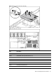
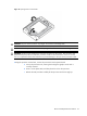
Cable Connections
The following table provides information about switching power supply cable connector labels.
Table 1 Personality Board Cable connections
Cable To Cable Designator
Power convert cable 24P Node 24-pin Power Connector J11
Power convert cable 8P Node 8-pin Power Connector J5
Power convert cable 4P Node 4-pin Power Connector J20
Front Board cable1, 12P Front IO Board Control Signal
Interface Connector
J2
Front panel I/O Cable2, 20P System Board Control Signal
Interface Connector
J12
RPS cable 16P System Board Power Supply
Management Interface Connector
J3
SATA/SAS Cable HDD Power Connector J14, J15, J16, J17, J18, J19, J21,
J22, J23, J24
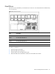
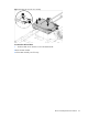
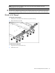
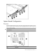
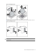
The following table provides the system board designators that various cables plug into. For more
detailed information about system board components, see system board components.
Table 2
Node Cable connections
Cable
To
System Board Designator
Power convert cable Node 24-pin Power Connector J51
Power convert cable Node 8-pin Power Connector J64
Power convert cable Node 4-pin Power Connector J60
FPIO Cable 2 System Board Control Signal
Interface Connector
J42
RPS cable System Board Power Supply
Management Interface Connector
J82
SATA cable 5 Node SATA5 J57
SATA cable 6 Node SATA6 J58
SAS cable 1 Node Mini SAS connector J11
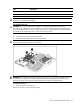
Table 3AC power board connection
Cable To System Board Designator
RCM cable RCM Connector J11
UID cable UID Connector J10
Fan cable Fan Control Signal and Power
Connector
J12, J16, J18, J22, J14,J19