
HP ProLiant SL160s G6 Server Maintenance and Service Guide

Removal and Replacement Procedures 38
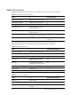
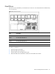
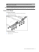
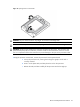
Item
Description
1 Processor 1
2 Processor 2
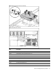
WARNING: To reduce the risk of personal injury from hot surfaces, allow the heat sink and the
processor to cool before touching them.
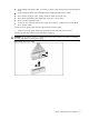
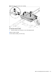
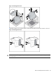
To remove the heat sink:
CAUTION: To prevent the heat sink from tilting to one side during installation and removal
procedures, use a diagonally opposite pattern (an “X” pattern) when loosening and tightening the
two spring-loaded screws. Do not over tighten the heat sink’s spring-loaded screws to prevent them
from breaking off. A maximum torque of 4 in-Ib is set for the system.
1. Loosen the two mounting pins.
2. Lift the heat sink away from the system board.
3. Lift the heat sink frame away from the system board.
CAUTION: Place heat sink down in an upright position with the thermal patch facing upward. Do
not let the thermal patch touch the work surface.
Figure 11 Removing the Heat Sink assembly
IMPORTANT: If the heat sink has been removed for any reason on a previously installed processor, it
is critical that you apply more thermal interface material to the integrated heat spreader on the
processor to ensure proper thermal bonding between the processor and the heat sink.
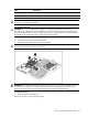
To remove a processor:
1. Open the processor locking lever.
2.Open the processor socket retaining bracket.