
HP ProLiant SL160s G6 Server Maintenance and Service Guide


Connectors, Switches, and LEDs 64
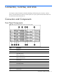
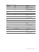
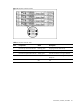
Item
Designator
Description
15 B1 CMOS Battery
16 J82 RPS connector
17 J65 BP I
2
C CONN
18 J42 FRONT PANEL CONN
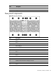
19 J67
J68
J70
J62
J71
Fan6 connector (from left to right)
Fan5 connector
Fan4 connector
Fan3 connector
Fan2 connector
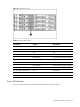
20 J64 12V POWER CONN
21 J57
J58
SATA5 connector
SATA6 connector
22 J63 FAN CONN
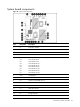
23 J74
J43
J44
J75
J45
J46
J76
J47
J48
CPU1 DIMM 1G slot (from left to right)
CPU1 DIMM 2D slot
CPU1 DIMM 3A slot
CPU1 DIMM 4H slot
CPU1 DIMM 5E slot
CPU1 DIMM 6B slot
CPU1 DIMM 7I slot
CPU1 DIMM 8F slot
CPU1 DIMM 9C slot
24 J51 SYSTEM POWER CONN
25 U73 Processor 1 Socket
26 J60 12V POWER CONN
27 U34 Processor 2 Socket
CAUTION: The TPM is not a customer-removable part.
Any attempt to remove an installed TPM from the system board breaks or disfigures the TPM security
rivet. Upon locating a broken or disfigured rivet on an installed TPM, administrators should consider
the system compromised and take appropriate measures to ensure the integrity of the system data.
If you suspect a TPM board failure, leave the TPM installed and remove the system board. Contact
an HP authorized service provider for a replacement system board and TPM board.
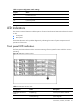
Jumpers Setting
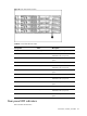
Table 4 describes the jumper settings.
Table 4 System configuration switch settings
Jumper Status
J27 A, Clear CMOS