HP ProLiant SL160s G6 Server Software Configuration Guide Part number 635242-001 First edition March 2011
Legal notices © Copyright 2011 Hewlett-Packard Development Company, L.P. The information contained herein is subject to change without notice. The only warranties for HP products and services are set forth in the express warranty statements accompanying such products and services. Nothing herein should be construed as constituting an additional warranty. HP shall not be liable for technical or editorial errors or omissions contained herein. Microsoft®, Windows®, and Windows Server® are U.S.
Contents System BIOS configuration .................................................................................................................... 4 System BIOS overview ................................................................................................................................. 4 BIOS software ............................................................................................................................................ 4 BIOS Setup Utility .............................
System BIOS configuration This chapter describes the basic functions of the BIOS. System BIOS overview A Basic Input/Output System, or BIOS, is a set of programs permanently stored in an EEPROM chip (U55) located on the system board. These programs serve as an interface between the server’s hardware components and its operating system. This ProLiant server features a ROM BIOS-based diagnostic tool that monitors system activity and performs constant hardware testing to ensure proper system operation.
NOTE: If you repeatedly receive “Run Setup” messages, the battery located on the system board (B1) may be defective. In this case, the system cannot retain configuration values in CMOS. Ask a qualified technician for assistance. The Setup Utility loads the configuration values in a battery-backed nonvolatile memory called CMOS RAM. This memory area is not part of the system RAM, which allows configuration data to be retained when power is turned off. The values take effect when the system is booted.
Table 1 Setup Utility navigation keys Key Function ← and → Move between selections on the menu bar. ↑ and ↓ Move the cursor to the field you want. The currently selected field is highlighted. The right side of each menu screen displays the Item Specific Help panel. This panel displays the help text for the selected field. It updates as you move the cursor to each field. <+>, <–> Select a value for the currently selected field if it is user-configurable.
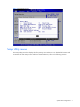
Figure 2 General Help Screen Setup Utility menus The Setup Utility menu bar displays the five primary menu selections. For detailed information and screenshots of these Setup menus and their related submenus, refer to the following sections.
Main Menu Figure 3 Main Menu (1) Figure 4 Main Menu (2) NOTE: The time is in 24-hour format. For example, 5:30 A.M. appears as 05:30:00, and 5:30, P.M. as 17:30:00. If you unplug the battery, setup time values will be 00:00:00.
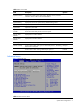
Table 2 Main menu fields Field Description Options System Overview Displays the product name of the system, the BIOS version, the date when this version of BIOS was built and ROM ID. Processor Displays the CPU version, speed and count. System Memory Displays the amount of system memory detected during POST. System Time Adjusts the system time. System Date Adjusts the system date. System Serial Number Displays the server serial number.
Field Description Power Efficiency Mode Efficiency/Performance: Impact groups as CPU Configuration/CPU bridge Configuration/PCI Express Configuration. Custom: Allow to configure Efficiency/Performance related items individually. CPU Configuration You can use this screen to select options for the CPU Configuration Settings. Use the up and down keys to select an item. Use the and keys to change the value of the selected option.
CPU Configuration submenu Figure 6 CPU Configuration submenu (1) Figure 7 CPU Configuration submenu (2) NOTE: The CPU Configuration setup screen varies depending on the installed processor.
Table 4 CPU Configuration submenu fields Field Description Options C1E Support This should be enabled in order to enable or disable the “Enhanced Halt State”. The Setting default value is Enabled. Enabled Disables the item. Disables support for adjacent cache line prefetch debug function. Disabled Enabled Hardware Prefetcher feature. Enabled This should be enabled in order to enabled or disable the Hardware Prefetcher Disable feature. The Setting default value is Enabled.
Table 4 CPU Configuration submenu fields Field Description Options C State package limit setting Select option will program into C State package limit register automatically Auto Select option will program into C1 State package limit register C1 Select option will program into C3 State package limit register C3 Select option will program into C6 State package limit register C6 Select option will program into C7 State package limit register C7 CPU Bridge Configuration submenu Figure 8 CPU Bridg
Table 5 CPU Bridge Configuration submenu fields Field Description Options Memory Frequency Forces a DDR3 frequency slower than the common tCK detected via SPD. Auto Force DDR-800 Force DDR-800 Force DDR-1066 Force DDR-1066 Force DDR-1333 Force DDR-1333 Independent: independent channel. Independent Mirroring: mirror channel space between channels. Channel Mirroring Lockstep: lockstep between channel 0 and 1 lockstep Configure memory controller to socket interleaved mode.
SATA Configuration submenu Figure 9 SATA Configuration submenu Table 6 SATA Configuration submenu fields Field Description Options SATA#1 Controller Disable SATA#1 controller Disabled Configure SATA#1 controller to compatible mode Compatible Configure SATA#1 controller to RAID mode RAID Configure SATA#1 controller to AHCI mode AHCI Disable SATA#2 controller Disabled Enable SATA#2 conroller Enabled Drive Write Cache feature disabled on all dumb SATA drives.
Super IO Configuration submenu Figure 10 Super IO Configuration submenu Table 7 IO Device Configuration submenu fields Option Description Options Embedded Serial Port Address Controls IRQ trigger for serial port. Use to resolve issues that may occur with Level Trigger serial port support. VMware requires Edge to provide optimum serial port performance. Note: Only applies with serial port at IRQ4. Edge Trigger Serial Port Set this value to prevent the serial port from accessing any system resources.
USB Configuration submenu Figure 11 USB Configuration submenu NOTE: When you install USB storage, USB Mass Device Configuration items are displayed. From this item, you can get some information about the device, some information you can configure it if needed. Table 8 USB Configuration submenu fields Field Description Options USB Functions Enable USB Functions. Enabled Disable USB Functions. Disabled Enables support for legacy USB. Enabled Disables support for legacy USB.
Table 8 USB Configuration submenu fields Field Description Options Support FDD later. Auto option creates this dummy device only if there is no FDD Enabled present. Disabled USB Mass Storage Device Configuration Configure the USB Mass Storage Class Devices. The settings are described on the following pages.
Table 9 USB Mass Storage Device Configuration submenu fields Field Description Options Emulations Type is CD ROM. CD ROM Device #2 Display USB Device name Emulation Type If Auto, USB devices less than 530MB will be emulated as Floppy and remaining as hard drive. Auto Emulation Type is Floppy. Floppy Forced FDD option can be used to force a HDD formatted drive to boot as FDD(Ex. ZIP dirve). Forced FDD Emulation Type is Hard Disk. Hard Disk Emulations Type is CD ROM.
Table 10 PCI Configuration submenu fields Field Description Options Embedded NIC Port 1 PXE The option specifies the embedded NIC Port1 PXE, Allows the user to enable of any embedded NIC Ports. Should be one SETUP option for each embedded NIC Port. Enabled The default setting is Enabled. The option specifies the embedded NIC Port1 PXE, Allows the user to disable of any embedded NIC Ports. Should be one SETUP option for each embedded NIC Port.
PCI Express Configuration submenu Figure 14 PCI Express Configuration submenu Table 11 PCI Express Configuration submenu fields Field Description Options Active State PowerManagement Enable PCI Express L0s and L1 link power states. Enabled Disable PCI Express L0s and L1 link power states. Disabled Gen2: For best possible performance. Gen 2 Gen1: All PCI-E devices will only run in Gen 1 mode.
IPMI Configuration submenu Figure 15 IPMI Configuration submenu Table 12 IPMI Configuration submenu fields Field Description Set LAN Configuration Select Set LAN Configuration in the left frame of the screen to go to the submenu for that item. You can display a submenu about LAN options by highlighting it using the keys. Set LAN Setup options are described in this section. The Set LAN BIOS Setup screen is shown below (When you have a LO100 Device, this item will display).
Figure 16 Set LAN Configuration submenu Table 13 Set LAN Configuration submenu fields Field Description Options BMC NIC Allocation Shared mode: allow IPMI remote functions to run through the onboard NIC’s network line. Shared Dedicated mode: allow IPMI remote functions to run through its own network line. Dedicated IP Address obtained by user configuration. Static IP Address obtained by BMC running DHCP. DHCP To enable BMC Telnet Service. Enabled To disable BMC Telnet Service.
Figure 17 SEL Configuration submenu (1) Figure 18 SEL Configuration submenu(2) Table 14 SEL Configuration submenu fields Field Description View BMC System Event Log The option specifies BMC system event log. Select this option and press to access the submenu to view the contents of System Event log. Clear BMC System Event Log The option specifies clear system event log. If the BMC Event log is full, you can choose this item to clear out the BMC Event log.
Figure 19 Hardware Health Information submenu Table 15 Hardware Health Information submenu fields Field Description Temperature Show a list of sensor temperature Fan Rotation Rate Show system Fan Rotation Rate Figure 20 Watchdog Configuration submenu Table 16 Watchdog Configuration submenu fields Field Description Options System BIOS configuration 25
Table 16 Watchdog Configuration submenu fields Field Description Options IPMI Watchdog Timer Set this value to allow BMC to reset if the operating system crashes or hangs. Reset System Disabled the item will not allow to crashes or hangs if OS crashes or hangs. This is the default setting. Disabled Set this value to allow BMC to power down if the operating system crashes or hangs. Power Down Set this value to allow BMC to power cycle if the operating system crashes or hangs.
Table 17 Serial Port Configuration submenu fields Field Description Options Serial Port Assignment This setting will assign the serial port connector to the system. The setting default value is System. System This setting will assign the serial port connector to the BMC (Baseboard BMC management controller). Serial Port Connection Mode Serial port connection mode is Direct. The setting default value is Direct. Direct Serial port connection mode is Modem.
BIOS Serial Console Configuration submenu Figure 22 BIOS Serial Console Configuration submenu (1) Figure 23 BIOS Serial Console Configuration submenu (2) Table 18 BIOS Serial Console Configuration submenu fields Field Description Options BIOS Serial Console When Enabled, can configure related settings Enabled Disable BIOS Serial Console type. Disabled Serial port number Select Serial Port For Console redirection. Make sure the selected port is enabled.
Table 18 BIOS Serial Console Configuration submenu fields Field Flow Control Redirection After BIOS POST Thermal Type VT-UTF8 Combo Key Support Sredir Memory Display Delay Description Options Select Serial Port setting as 57600 8,n,1 57600 8,n,1 Select Serial Port setting as 19200 8,n,1 19200 8,n,1 Select Serial Port setting as 09600 8,n,1 09600 8,n,1 No flow control None Enable RTS/CTS hardware flow control Hardware Enable RTS/CTS software flow control Software Turns off the redirection
Trusted Computing submenu Figure 24 Trusted Computing submenu Table 18 Trusted Computer Configuration submenu fields Field Description Options TCG/TPM SUPPORT Enable/Disable TPM TCG (TPM 1.1/1.
Boot Menu Figure 25 Boot Menu Table 19 Boot menu fields Field Description Boot Settings Configuration Sets which options to run during system boot up. Press Enter to access the related submenu. For details on the submenu options, see the “Hard Disk Drives configuration submenu” section. Standard Boot Order Specifies the Boot Device Priority sequence. Hard Disk Drives Specifies the boot Device Priority sequence from available Hard Drives.
Figure 26 Standard Boot Order submenu NOTE: When you select a boot category from the boot menu, a list of devices in that category appears. Hard Disk Drives configuration submenu Figure 27 Hard Disk Drives Configuration submenu Security menu The Security menu allows users to set an administrator password. When entered, this password allows the user to access and change all settings in the Setup Utility.
Figure 28 Security menu System BIOS configuration 33
To set an administrator password: 1. Indicates whether a supervisor password has been set, if the password has been installed, installed displays, if not, not installed displays. 2. In the Security menu screen, in the Change Admin Password field, press Enter. The Enter New Password window displays. Figure 29 Enter New Password 3. Type a new password in the Enter New Password box. The password may consist of up to six alphanumeric characters (A-Z, a-z, 0-9), then press Enter.
Figure 30 Confirm New Password 4. Type the same password in the Confirm New Password box to verify the first entry, and then press Enter. The Password Installed OK is displayed. Press OK to finish. Figure 31 Password installed 5. Press F10 to save the password and close the Setup Utility. Setup automatically changes the administrator Password.
To change the Admin Password: 1. In the Security menu screen, in the Change Admin Password field, press Enter. The Enter New Password displays. Type a new password in the Enter New Password box. 2. Type the same password in the Confirm New Password box to verify the first entry, then press Enter. The Password Installed OK is displayed. Press Enter to finish. To check the administrator password: 1. In the Security menu screen, select Password Check, and then press Enter. 2.
Exit menu The Exit menu displays several options on how to quit the Setup Utility. Select any of the exit options then press Enter. Figure 33 Exit menu Table 21 Exit menu fields Option Description Save Changes and Exit Save the changes made and exit the Setup Utility. Discard Changes and Exit Discard the changes and exit the setup utility. Discard Changes Discard the changes in the utility. Restore Default Setting Restore the default settings for all BIOS setup fields.
To load the system defaults: 1. Reboot the server in a normal manner. 2. During POST, press F10 to access the Setup Utility. 3. Press F9 to load the default values. 4. Press F10 to save the changes and close the Setup Utility. Clearing CMOS You may need to clear the Setup configuration values (CMOS) if the configuration has been corrupted, or if incorrect settings made in the Setup Utility have caused error messages to be unreadable. Clearing the CMOS data removes the administrator password.
In some cases an error message may include recommendations for troubleshooting or require that you press the Enter key to display recommendations. Follow the instructions on the screen. It is recommended that you correct the error before proceeding, even if the server appears to boot successfully. If your system displays one of the messages marked below with an asterisk (*), write down the code and message and contact your HP Customer Support provider.
Table 22 POST error message 601 Error: BMC Not Responding 041 Display memory test failed 040 Refresh timer test failed 048 Password check failed 00B CMOS Memory Size Wrong 010 Floppy Controller Failure 00C RAM R/W test failed 003 CMOS Battery Low 701 Insufficient Runtime space for MPS data. System may operate in PIC or Non-MPS mode. 702 No enough APIC ID in range 0-0Fh can be assigned to IO APICs.
OS installation Supported OS Table 23 Supported network operating systems (NOS) NOS Version On-line information site Microsoft Windows • Microsoft Windows Server 2008, Standard Microsoft World Wide Web: Edition (x86 and x64) – SP2 and R2 w/SP1 • Microsoft Windows Server 2008, Enterprise http://www.microsoft.com Edition (x86 and x64) - SP2 and R2 w/SP1 Microsoft Product Easy Setup Services: http://www.Easy Setup.microsoft.
Hardware setup Prepare the server following the instructions in the HP ProLiant SL160s G6 Server Installation Sheet. It is recommended that you do not install any third party adapter until you verify that the HP equipment is functioning properly and you complete the OS installation. Your ProLiant server comes with new hard disk drive(s) that do not need specific setup.
Server management Pre- and post-installation procedures Pre-installation procedures WARNING: Failure to properly turn off the server before you open the server or before you start removing or installing hardware components may cause serious damage as well as bodily harm. WARNING: To reduce the risk of personal injury from hot surfaces, allow the chassis and any installed hardware components to cool before touching them.
To configure the BMC through the Setup Utility: 1. In the Serial Port Configuration submenu under the IPMI Configuration submenu, set the Serial port Assignment field to System or BMC. See the “Serial Port Configuration submenu fields” section for more information. 2. In the LAN Configuration Settings submenu under the IPMI configuration submenu, set the IP address, default gateway, and IP subnet mask for the BMC. You can set the addresses manually or use DHCP to set the addresses automatically. 3.
1. In the Serial Port Configuration submenu under the IPMI Configuration submenu, set the Serial port Assignment field to System or BMC. See the “Serial Port Configuration submenu fields” section for more information. 2. In the Console Redirection submenu, set Remote Access to Enable. See the “Console Redirection submenu fields” section for more information. 3. Press F10 to Save and Exit.
Index A administrator password, 32 IP subnet mask, 44 IPMI Configuration submenu, 22 administrator password changing, 36 IPMI LAN interface, 44 administrator password checking, 36 L Advanced menu, 9 LAN Controller, 44 B M Baseboard management controller, 27 Main Menu, 8 Basic Input/Output System, 4 memory, 9 BIOS EHCI Hand-Off, 17 N BIOS overview, 4 BIOS Serial Console Configuration submenu, 28 BIOS Setup Utility, 4 BIOS update, 42 BMC Watchdog Timeout, 26 New Password box, 34 O operating
system configuration changing, 4 U System Date, 9 USB Configuration submenu, 17 system defaults, 37 V System Time, 9 system time and date setting, 4 T Trusted Computing submenu, 30 View BMC System Event Log, 24 W Watchdog Configuration, 22 Index 47