HP ProLiant SL165s G7 Server Installation Instructions Part Number 635251-002
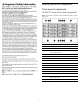
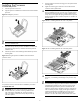
Identifying server components Front panel components SL165s G7 Server Front Panel Components Figure 1 Front panel components of the s6500 chassis with 4 SL165s G7 servers 2 Item Description 1 UID LED/Switch 2 Serial port 3 Top: NIC4 Connector Bottom: NIC3 Connector 4 Server 1 5 Server 2 6 Server 3 7 Power LED/Switch 8 Health LED 9 NIC1 Connector 10 NIC2 Connector 11 Server 4 12 VGA port 13 Mgmt NIC (Optional) 14 Top: USB 2.0 Port Bottom: USB 2.
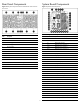
Rear Panel Components System Board Components Figure 2 Rear panel components of the s6500 chassis with 4 SL165s G7 servers Figure 3 System Board Components Item Designator Description 1 J1 System maintenance jumper 2 J301 PCIe x16 slot 3 U1 Processor 1 4 J11 Mgmt card connector Power Supply 2 5 J110 DIMM slot 12 for processor 1 5 Power Supply 3 6 J103 DIMM slot 1 for processor 1 6 Fan 2 7 J210 DIMM slot 12 for processor 2 7 Fan 1 8 U2 Processor 2 8 Fan 3 9 J54 4-pin
Server Configuration Resources In addition to this Installation Sheet, other resources are available for more information regarding the configuration and maintenance of your server: • • • • 5. Connect all external cables to the system. 6. Press the power button on the front panel to turn on the server.
NOTE: NOTE: For specific supported hard drive configurations and cable routing, refer to HP ProLiant SL165s G7 Server Maintenance and Service Guide located on the HP website: http://www.hp.com/support/ProLiant_SL165sG7_MSG_en SR = Single Rank, DR = Dual Rank, QR = Quad Rank. Population rules must be followed for both processors. Memory modules may be populated one at a time per processor, but populating two at a time per processor provides better performance.
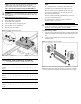
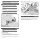
Installing the Processor To install the new processor: 1. Insert the processor in the tool. 2. Align the processor installation tool with the socket and install the processor. 1. Properly align the heat sink mounting pins to the system board mounting holes. 2. Tighten the mounting pins clockwise to secure the heat sink connection to the system board.
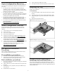
Figure 13 Installing the CPU air baffle into the tray NOTE: Do not over tighten the heat sink’s spring-loaded screws to prevent them from breaking off. Installing the DIMM Air Baffle NOTE: The DIMM air baffle is required for proper thermal solution. 1. Hold the latch on the top of the DIMM air baffle and align it to the system board. 2. Press down to make sure the DIMM air baffle completely installed NOTE: To check and ensure the 2 ribs are installed between DIMM1 and DIMM2, DIMM11 and DIMM12.
Legal notices © Copyright 2010, 2011 Hewlett-Packard Development Company, L.P. The information contained herein is subject to change without notice. The only warranties for HP products and services are set forth in the express warranty statements accompanying such products and services. Nothing herein should be construed as constituting an additional warranty. HP shall not be liable for technical or editorial errors or omissions contained herein.