
HP ProLiant SL165s G7 Server Installation Instructions

3
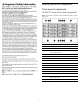
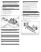
Rear Panel Components
Figure 2 Rear panel components of the s6500 chassis with 4 SL165s
G7 servers
Item Description
1 Fan 6
2 Fan 5
3 Power Supply 1
4 Power Supply 2
5 Power Supply 3
6 Fan 2
7 Fan 1
8 Fan 3
9 Fan 4
10 Power Blank
11 Chassis UID
12 SLAPM (SL Advanced Power Manager) connector
13 Fan 7
14 Fan 8
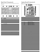
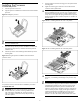
System Board Components
Figure 3 System Board Components
Item Designator Description
1
J1
System maintenance jumper
2 J301 PCIe x16 slot
3
U1
Processor 1
4 J11 Mgmt card connector
5
J110
DIMM slot 12 for processor 1
6
J103
DIMM slot 1 for processor 1
7
J210
DIMM slot 12 for processor 2
8 U2 Processor 2
9
J54
4-pin power connector
10 J52 24-pin power connector
11
J61
Fan connector 1
12
J62
Fan connector 2
13
J203
DIMM slot 1 for processor 2
14 J68 Backplane I
2
C connector
15
J53
8-pin power connector
16 J63, J64 Fan connectors 3/4
17
J65
Fan connector 5
18
J49
Internal USB 2.0 port
19
J8
Front panel USB 2.0 port
20 J81 SD card USB 2.0 port
21
J100
SAS LED connector
22 J66, J69 Fan connectors 6/7
23
J55
Power backplane control connector
24
J13
Mini-SAS connector for SATA
25
J98
Front panel header
26 J56 TPM connector
27
J78
PCIe x4 slot
28 J23 ODD 1 SATA connector
29
J20
ODD 2 SATA connector
30 BH1 3V CMOS battery (CR2032)
31 J6 NMI jumper