HP ProLiant SL165s G7 Server Software Configuration Guide Part number 635254-001 First edition March 2011
Legal notices © Copyright 2011 Hewlett-Packard Development Company, L.P. The information contained herein is subject to change without notice. The only warranties for HP products and services are set forth in the express warranty statements accompanying such products and services. Nothing herein should be construed as constituting an additional warranty. HP shall not be liable for technical or editorial errors or omissions contained herein. Microsoft®, Windows®, and Windows Server® are U.S.
Contents System BIOS configuration .................................................................................................................... 4 System BIOS overview ................................................................................................................................. 4 BIOS software ............................................................................................................................................ 4 BIOS Setup Utility .............................
System BIOS configuration This chapter describes the basic functions of the BIOS. System BIOS overview A Basic Input/Output System, or BIOS, is a set of programs permanently stored in an EEPROM chip (U55) located on the system board. These programs serve as an interface between the server’s hardware components and its operating system. This ProLiant server features a ROM BIOS-based diagnostic tool that monitors system activity and performs constant hardware testing to ensure proper system operation.
NOTE: If you repeatedly receive “Run Setup” messages, the battery located on the system board (B1) may be defective. In this case, the system cannot retain configuration values in CMOS. Ask a qualified technician for assistance. The Setup Utility loads the configuration values in a battery-backed nonvolatile memory called CMOS RAM. This memory area is not part of the system RAM, which allows configuration data to be retained when power is turned off. The values take effect when the system is booted.
Table 1 Setup Utility navigation keys Key Function ← and → Move between selections on the menu bar. ↑ and ↓ Move the cursor to the field you want. The currently selected field is highlighted. The right side of each menu screen displays the Item Specific Help panel. This panel displays the help text for the selected field. It updates as you move the cursor to each field. <+>, <–> Select a value for the currently selected field if it is user-configurable.
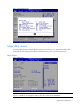
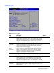
Figure 2 General Help Screen Setup Utility menus The Setup Utility menu bar displays the five primary menu selections. For detailed information and screenshots of these Setup menus and their related submenus, refer to the following sections. Main Menu Figure 3 Main Menu NOTE: The time is in 24-hour format. For example, 5:30 A.M. appears as 05:30:00, and 5:30, P.M. as 17:30:00. If you unplug the battery, setup time values will be 00:00:00.
Table 2 Main menu fields Field Description Product Name Displays the product name of the system. Processor Displays the CPU version, speed and count. System Memory Displays the amount of system memory detected during POST. System Time Adjusts the system time. System Date Adjusts the system date. ProLiant BIOS Display the date when this version of BIOS was built, the BIOS version, the system serial number and the MAC addresses of NIC1, NIC2, NIC3 and NIC4.
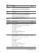
Advanced menu Figure 4 Advanced menu Table 3 Advanced menu fields Field Description Options CPU Configuration You can use this screen to select options for the CPU Configuration Settings. Use the up and down keys to select an item. Use the and keys to change the value of the selected option. A description of the selected item appears on the right side of the screen. The settings are described on the following pages.
Table 3 Advanced menu fields Field Description Remote Access You can select console redirection in the left frame of the screen to go to the sub menu for that item. You can display a console redirection by highlighting it using the keys .Console redirection Setup options are described in this section. The settings are described on the following pages. Configuration Options Trusted Platform Module Configure trusted platform module. The settings are described on the following pages.
CPU Configuration submenu Figure 5 CPU Configuration submenu NOTE: The CPU Configuration setup screen varies depending on the installed processor. Table 4 CPU Configuration submenu fields Field Description Module Version Display the module version. Physical Count Display the physical count. Logical Count Display the logical count. CPU Information Select which physical CPU’s information to display. Note: Zero is always the “Boot Strap Processor” or main CPU. All others are “Application Processors”.
Table 4 CPU Configuration submenu fields Field Description Options Hardware Prefetcher Enable the hardware components that are used in conjunction with software programs to prefetcher data in order to shorten execution cycles and maximize data processing efficiency. Enabled Disable the hardware components that are used in conjunction with software programs to prefetcher data in order to shorten execution cycles and maximize data processing efficiency.
SATA Configuration submenu Figure 6 SATA Configuration submenu Table 5 SATA Configuration submenu fields Field Description Options SATA Controller Disable SATA controller Disabled Configure SATA controller to compatible mode Compatible Configure SATA controller to RAID mode RAID Configure SATA controller to AHCI mode AHCI Mode Embedded SAS/SATA Link Rate Drive Write Cache System BIOS automatically sets the highest possible link rate based AUTO on the chipset and drives installed.
Memory Configuration submenu Figure 7 Memory Configuration submenu Table 6 Memory Configuration submenu fields Field Description Memory Configuration Configure memory settings. Advanced ECC Configuration Configure ECC settings. DRAM Timing Configuration Configure memory clock frequency.
AHCI Configuration submenu Figure 8 AHCI Configuration submenu Table 7 AHCI Configuration submenu fields Field Description AHCI BIOS Support Configure the AHCI BIOS Support settings. AHCI port0 While entering setup, BIOS auto detects the Presence of IDE devices. This option displays the status of auto detection of IDE devices.
IPMI Configuration submenu Figure 9 IPMI Configuration submenu Table 8 IPMI Configuration submenu fields Field Description BMC Firmware Revision Display the current status of BMC. BMC/IPMI FW Date Display the date of the BMC/IPMI firmware. BMC SDR Version Display the current version of the BMC SDR. Set LAN Configuration Access the submenu to configure Option of Set LAN Configuration. SEL Configuration Access the submenu to configure Option of SEL Configuration.
Figure 10 Set LAN Configuration submenu Table 9 Set LAN Configuration submenu fields Field Description Options BMC NIC Allocation Shared mode: allow IPMI remote functions to run through the onboard NIC’s network line. Shared Dedicated mode: allow IPMI remote functions to run through its own Dedicated network line. BMC LAN Configuration IP Address obtained by user configuration. Static IP Address obtained by BMC running DHCP. DHCP IP Address Enter IP address in decimal in the form of XXX.XXX.XXX.
Figure 11 SEL Configuration submenu (1) Figure 12 SEL Configuration submenu(2) Table 10 SEL Configuration submenu fields Field Description View BMC System Event Log The option specifies BMC system event log. Select this option and press to access the submenu to view the contents of System Event log. Clear BMC System Event Log The option specifies clear system event log. If the BMC Event log is full, you can choose this item to clear out the BMC Event log.
Figure 13 Hardware Health Information submenu Table 11 Hardware Health Information submenu fields Field Description Temperature Show a list of sensor temperature Fan Rotation Rate Show system Fan Rotation Rate Figure 14 Watchdog Configuration submenu Table 12 Watchdog Configuration submenu fields Field Description Options System BIOS configuration 19
Table 12 Watchdog Configuration submenu fields Field Description Options IPMI Watchdog Timer Set this value to allow BMC to reset if the operating system crashes or hangs. Reset System Disabled the item will not allow to crashes or hangs if OS crashes or hangs. This is the default setting. Disabled Set this value to allow BMC to power down if the operating system crashes or hangs. Power Down Set this value to allow BMC to power cycle if the operating system crashes or hangs.
Table 13 Serial Port Configuration submenu fields Field Description Options Serial Port Assignment This setting will assign the serial port connector to the system. The setting default value is System. System This setting will assign the serial port connector to the BMC (Baseboard BMC management controller). Serial Port Connection Mode Serial port connection mode is Direct. The setting default value is Direct. Direct Serial port connection mode is Modem.
PCI Express Configuration submenu Figure 16 PCI Express Configuration submenu Table 14 PCI Express Configuration submenu fields Field Description Options Embedded VGA Control Select which graphics controller to use as the primary boot device. Auto Detect Always enable on board VGA. Always Enabled Enable IOMMU (Input/Output Memory Management Unit) implementation for address translation and protection services.
Remote Access Configuration submenu Figure 17 Remote Access Configuration submenu (1) Table 15 Remote Access Configuration submenu fields (1) Field Description Options BIOS Serial Console When Enabled, can configure related settings Enabled Disable BIOS Serial Console type. Disabled NOTE: Figure 18 shows the Remote Access Configuration submenu when the BIOS Serial Console enabled.
Figure 18 Remote Access Configuration submenu (2) Table 16 Remote Access Configuration submenu fields (2) Field Description Options BIOS Serial Console Baud Rate Set this value to allow you to select 115200 as the Baud Rate (transmitted bits per second) of the serial port. 115200 8,n,1 Set this value to allow you to select 57600 as the Baud Rate (transmitted bits per second) of the serial port.
Table 16 Remote Access Configuration submenu fields (2) Field VT-UTF8 Combo Key Support Sredir Memory Display Delay Description Options Select the target Terminal Type to VT100. This item disappears when Remote is disabled. VT100 Select the target Terminal Type to VT-UTF8. This item disappears when Remote Access is disabled. VT-UTF8 Disable VT-UTF8 Combination Key Support for ANSI/VT100 terminals. Disabled Enable VT-UTF8 Combination Key Support for ANSI/VT100 terminals. This is the default setting.
USB Configuration submenu Figure 20 USB Configuration submenu NOTE: When you install USB storage, USB Mass Device Configuration items are displayed. From this item, you can get some information about the device, some information you can configure it if needed. Table 18 USB Configuration submenu fields Field Description Options USB BIOS Support Disable support for legacy USB. Disabled Enable support for legacy USB.
OnBoard Peripherals Configuration submenu Figure 21 OnBoard Peripherals Configuration submenu Table 19 OnBoard Peripherals Configuration submenu fields Field Description Options Embedded NIC Port 1 Control Disable onboard NIC port 1. Disabled Enable onboard NIC port 1. Enabled Disable onboard NIC port 1 PXE. Disabled Enable onboard NIC port 1 PXE. Enabled Allow wake up in S4/S5 over LAN. This is the default setting. Enabled Disabled Wake-On LAN in S4/S5.
Boot Menu Figure 22 Boot Menu Table 20 Boot menu fields Field Description Options Boot Settings Configuration Sets which options to run during system boot up. Press Enter to access the related submenu. For details on the submenu options, see the “Boot Device Priority submenu” section. Boot Device Priority Use this screen to specify the order in which the system checks for a boot device. Hard Disk Drives Specifies the boot Device Priority sequence from available Hard Drives.
Boot Settings Configuration submenu Figure 23 Boot Settings Configuration submenu Table 21 USB Configuration submenu fields Field Description Options Post Speed Up Execute the certain tests during POST. Disabled Allow BIOS to skip certain tests while booting. This is the default setting. Enabled Disable the Splash Screen function. Disabled Enable the Splash Screen function. Enabled Disable Power-on state for Numlock. Off Select Power-on state for Numlock.
Figure 24 Boot Device Priority submenu NOTE: When you select a boot category from the boot menu, a list of devices in that category appears. Security menu The Security menu allows users to set a supervisor password. When entered, this password allows the user to access and change all settings in the Setup Utility.
To set a Supervisor password: 1. Indicates whether a supervisor password has been set, if the password has been installed, installed displays, if not, not installed displays. 1. In the Security menu screen, in the Change Supervisor Password field, press Enter. The Enter New Password window displays. Figure 26 Enter New Password 2. Type a new password in the Enter New Password box. The password may consist of up to six alphanumeric characters (A-Z, a-z, 0-9), then press Enter.
Exit menu The Exit menu displays several options on how to quit the Setup Utility. Select any of the exit options then press Enter. Figure 27 Exit menu Table 22 Exit menu fields Option Description Save Changes and Exit Save the changes made and exit the Setup Utility. Discard Changes and Exit Discard the changes and exit the setup utility. Discard Changes Discard the changes in the utility. Restore Default Setting Restore the default settings for all BIOS setup fields.
To load the system defaults: 1. Reboot the server in a normal manner. 2. During POST, press F10 to access the Setup Utility. 3. Press F9 to load the default values. 4. Press F10 to save the changes and close the Setup Utility. Clearing CMOS You may need to clear the Setup configuration values (CMOS) if the configuration has been corrupted, or if incorrect settings made in the Setup Utility have caused error messages to be unreadable. Clearing the CMOS data removes the administrator password.
ensure that the server is properly functioning. This diagnostic function automatically runs each time the server is powered on. These diagnostics, which reside in the BIOS ROM, isolate server-related logic failures and indicate the board or component that needs to be replaced, as indicated by the error messages. Most server hardware failures are accurately isolated during POST. The number of tests displayed depends on the configuration of the server.
Table 23 POST error message 601 Error: BMC Not Responding Please check Front panel, System ID Jumper or Riser card Press F1 to Continue 628 Redundant Power Supply Mismatch 194 CPUID, Processor family are different 192 L3 cache size mismatch 197 Processor speeds mismatched 198 Processor QPI speed mismatch detected. 193 CPUID, Processor stepping are different 196 CPUID, Processor Model are different 195 Front side bus mismatch. System halted.
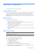
OS installation Supported OS Table 24 Supported network operating systems (NOS) NOS Version On-line information site Microsoft Windows • Microsoft Windows Server 2008, Standard Microsoft World Wide Web: Edition (x86 and x64) – SP2 and R2 w/SP1 • Microsoft Windows Server 2008, Enterprise http://www.microsoft.com Edition (x86 and x64) - SP2 and R2 w/SP1 Microsoft Product Easy Setup Services: http://www.Easy Setup.microsoft.
Your ProLiant server comes with new hard disk drive(s) that do not need specific setup. However, if you install additional used hard disk drives in your new server: • Note that most NOS installations remove all data from the hard disk on which they are installed. If you want to use additional hard disk drives to access existing data in the new server, HP recommends that you install and configure any of these hard drives after completing the NOS installation.
Server management Pre- and post-installation procedures Pre-installation procedures WARNING: Failure to properly turn off the server before you open the server or before you start removing or installing hardware components may cause serious damage as well as bodily harm. WARNING: To reduce the risk of personal injury from hot surfaces, allow the chassis and any installed hardware components to cool before touching them.
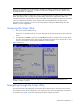
To configure the BMC through the Setup Utility: 7. In the Serial Port Configuration submenu under the IPMI Configuration submenu, set the Serial port Assignment field to System or BMC. See the “Serial Port Configuration submenu fields” section for more information. 8. In the LAN Configuration Settings submenu under the IPMI configuration submenu, set the IP address, default gateway, and IP subnet mask for the BMC. You can set the addresses manually or use DHCP to set the addresses automatically. 9.
1. In the Serial Port Configuration submenu under the IPMI Configuration submenu, set the Serial port Assignment field to System or BMC. See the “Serial Port Configuration submenu fields” section for more information. 2. In the Console Redirection submenu, set Remote Access to Enable. See the “Console Redirection submenu fields” section for more information. 3. Press F10 to Save and Exit.
Index A E Active Processor Cores, 12 Embedded NIC Port 1 Control, 27 Advanced menu, 9 Embedded NIC Port 1 PXE, 27 AHCI Configuration, 9 Embedded Serial Port, 21 AMD IOMMU, 22 Embeded VGA Control, 22 AMD Virtualization (AMD-V), 11 Exit menu, 32 ASPM Mode, 22 F asset tag, 8 B Baseboard management controller, 21 Basic Input/Output System, 4 BIOS overview, 4 BIOS Setup Utility, 4 BIOS update, 37 BMC Firmware Revision, 16 Fan Control Policy, 16 G General Help Screen, 7 H Hard Disk Drives, 28 Ha
Physical Count, 11 software, 4 POST, 33 Splash Screen, 29 POST error message, 34 supervisor password, 30 Post Speed Up, 29 supervisor password changing, 31 POST Watchdog Timer Action, 20 supervisor password clearing, 31 Power Capping, 11 system configuration changing, 4 Power Efficiency Model, 10 System Date, 8 PowerNow, 11 system defaults, 32 Processor, 8 System Memory, 8 Product Name, 8 System Time, 8 ProLiant BIOS, 8 system time and date setting, 4 R T Remote Access Configuration,