HP ProLiant SL165z G6 Server Software Configuration Guide Part number 577859-001 First edition November 2009
Legal notices © Copyright 2009 Hewlett-Packard Development Company, L.P. The information contained herein is subject to change without notice. The only warranties for HP products and services are set forth in the express warranty statements accompanying such products and services. Nothing herein should be construed as constituting an additional warranty. HP shall not be liable for technical or editorial errors or omissions contained herein. AMD is a trademark of Advanced Micro Devices, Inc.
Contents System BIOS configuration ...................................................................................................................... 4 System BIOS overview .............................................................................................................................. 4 AMIBIOS software ................................................................................................................................... 4 AMIBIOS Setup Utility..................................
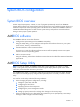
System BIOS configuration System BIOS overview A Basic Input/Output System, or BIOS, is a set of programs permanently stored in an EEPROM chipset (XU3) located on the system board. These programs serve as an interface between the server’s hardware components and its operating system. This ProLiant server features the AMIBIOS software— a ROM BIOS-based diagnostic tool that monitors system activity and performs constant hardware testing to ensure proper system operation.
NOTE: If you repeatedly receive “Run Setup” messages, the battery located on the system board (XBAT1) may be defective. In this case, the system cannot retain configuration values in CMOS. Ask a qualified technician for assistance. The Setup Utility loads the configuration values in a battery-backed nonvolatile memory called CMOS RAM. This memory area is not part of the system RAM, which allows configuration data to be retained when power is turned off. The values take effect when the system is booted.
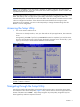
Table 1 Setup Utility navigation keys Key Function ← and → Move between selections on the menu bar. ↑ and ↓ Move the cursor to the field you want. The currently selected field is highlighted. The right side of each menu screen displays the Item Specific Help panel. This panel displays the help text for the selected field. It updates as you move the cursor to each field. <+>, <–> Select a value for the currently selected field if it is user-configurable.
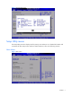
Figure 2 General Help Screen Setup Utility menus The Setup Utility menu bar displays the five primary menu selections. For detailed information and screenshots of these Setup menus and their related submenus, refer to the following sections.
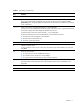
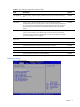
NOTE: The time is in 24-hour format. For example, 5:30 A.M. appears as 05:30:00, and 5:30, P.M. as 17:30:00. If you clear CMOS battery, setup time values will be 00:00:00 and date will be BIOS release date. If you clear CMOS button, setup time and date will not be changed. Table 2 Main menu fields Field Description System Overview Displays the system ROM Version, the date when the Setup utility was created and identification number. Processor Displays the CPU version and speed.
Table 3 Boot Settings Configuration submenu fields Field Description Options Post Speed Up Set this value to not allow display hardware summary screen before booting the OS. Enabled Set this value to allow displays hardware summary screen before booting the OS Disabled Set this value to allow the Number Lock on the keyboard to be enabled automatically when the computer system is boot up. This allows the immediate use of 10-keys numeric keypad located on the right side of the keyboard.
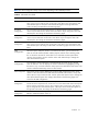
NOTE: The CPU Configuration setup screen varies depending on the installed processor. Table 4 Advanced menu fields Field Description CPU Configuration You can use this screen to select options for the CPU Configuration Settings. Use the up and down keys to select an item. Use the and keys to change the value of the selected option. A description of the selected item appears on the right Side of the screen. The settings are described on the following pages.
CPU Configuration submenu Figure 6 CPU Configuration submenu Table 5 CPU Configuration submenu fields Field Description Options AMD(R) Virtualization (AMD-V) Set this value to Disable Secure Virtual Machine Mode (SVM). Disabled Set this value to Enable Secure Virtual Machine Mode (SVM). Enabled This mode provides the highest level of performance but does not fully support x4 Chipkill.
Figure 7 Super IO Device Configuration submenu Field Description 3F8/IRQ4 Set this value to allow the serial port to use 3F8 as its I/O port address and IRQ 4 for the interrupt address. This is the default setting. The majority of serial port 1 or COM1 ports on computer systems use IRQ4 and I/O Port 3F8 as the standard setting. The most common serial device connected to this port is a mouse. If the system will not use a serial device, it is best to set this port to Disabled.
S-ATA Configuration submenu Figure 8 S-ATA Configuration submenu Table 6 S-ATA Configuration submenu fields Field Description Options S-ATA mode Set this value to S-ATA mode S-ATA Set this value to P-ATA mode P-ATA Set this value to enabled INT13 support Enabled Set this value to disabled INT13 support Disabled Set this value to enabled NCQ Mode Enabled Set this value to disabled NCQ Mode Disabled Set this value to enabled Write Back Cache Mode Enabled Set this value to disabled Write Bac
Table 7 ACPI Configuration submenu fields Field Description Options High Precision Event Timer Disable HPET Disabled Enable HPET Enabled IPMI Configuration submenu Figure 10 IPMI Configuration submenu Contents 14
Table 8 IPMI Device Configuration submenu fields Field Description SEL Configuration Select SEL configuration in the left frame of the screen to go to the sub menu for that item. Then you can press Enter to enter its sub-menu. You can display an about SEL Configuration option by highlighting it using the keys. Serial Port Configuration Select serial port configuration in the left frame of the screen to go to the sub menu for that item. Then you can press Enter to enter its sub-menu.
Table 9 SEL Configuration submenu fields Field Description View BMC System Event Log The option specifies BMC system event log. Select this option and press to access the sub menu you can view the contents of System Event log. Clear BMC System Event Log The option specifies clear system event log. If the BMC Event log is full, you can choose this item to clear out the BMC Event log. If this option is selected, a confirmation prompt will appear before the log is cleared.
Table 10 Serial Port Configuration submenu fields Options Field Description Serial Port Assignment This setting will assign the serial port connector to the system. This is System the default setting. Serial Port Switching Serial Port Connection Mode This setting will assign the serial port connector to the BMC (Baseboard management controller). BMC This setting allows the Serial port switch between system and BMC.
Figure 14 Watchdog Configuration submenu Table 12 Watchdog Configuration submenu fields Field Description Options POST Watchdog Timer Action Set this value to allow BMC to reset if the operating system crashes or hangs. This is the default setting. Reset System Disabling this option disables any BMC action if OS crashes or hangs. Disabled Set this value to allow BMC to power down if the operating system crashes or hangs.
Figure 15 Hardware health information submenu(1 Figure 16 Hardware health information submenu(2) Contents 19
Figure 17 Hardware health information submenu(3) Console Redirection submenu Figure 18 Console Redirection submenu Contents 20
Table 13 Console Redirection submenu fields Field Description Options Console Redirection Setting this value will allow configure the serial port. Enabled Setting this value will prevent configure the serial port. This is Disabled the default value. EMS support(SPCR) Enable EMS support. Include ACPI SPCR table pointer to RSDT pointer list. Disabled Disable EMS support.
NOTE: when you install USB storage, there is display USB Mass Device Configuration item, from this item, you can get some information about the device, some information you can configure it if you need. Table 14 USB Configuration submenu fields Field Description Options USB Ports This setting allows the use of the USB function. This is the default setting. Enabled This setting makes the onboard USB function unavailable. Disabled Enables support for legacy USB.
Table 15 PCI BUS Configuration submenu fields Field Description Options Embedded VGA Control System only boot from embedded Video device. Always Enabled System boot from Video card when found it. Auto Detect Power Configuration submenu Figure 21 Power Configuration Menu Table 16 Power Configuration submenu fields Field Description Options Power Efficiency Mode Maximize the performance per Watt value as measured by SpecPower. Efficiency Maximize the performance of the server.
Figure 22 Boot Menu Table 17 Boot Menu fields Field Description Boot Device Priority Use this screen to specify the order in which the system checks for the device to boot from. To access this screen, select Boot Device priority on the Boot setup screen and press , the following screen displays. Embedded NIC Port 1 PXE The option specifies the embedded NIC Port 1 PXE .the default is enabled. Embedded NIC Port 2 PXE The option specifies the embedded NIC Port 2 PXE .the default is disabled.
Figure 23 Boot Device Priority submenu NOTE: When you select a boot category from the boot menu, a list of devices in that category appears. For example, if the system has three hard disk drives connected, then the list will show all three hard disk drives attached. Security menu The Security menu allows users to set an administrator password. When entered, this password allows the user to access and change all settings in the Setup Utility.
To set an administrator password: 1. Indicates whether a supervisor password has been set, if the password has been installed, installed displays, if not, not installed displays. In the Security menu screen, in the Change Administrator Password field, press Enter. The Enter New Password window displays Figure 25 Enter New Password 2. Type a new password in the Enter New Password box.
3. Type the same password in the Confirm New Password box to verify the first entry, and then press Enter. The Password Installed OK windows display, press OK finish the password installed. Figure 27 Password installed 4. Press F10 to save the password and close the Setup Utility. Setup automatically changes the administrator Password Is field to set. To change the administrator password: 1. In the Security menu screen, in the Change Administrator Password field, press Enter.
To clear the administrator password: 1. In the Security menu screen, in the Change Administrator Password field, press Enter. The Enter New Password window displays. Directly press Enter button. To check the administrator password: Figure 28 Password Check submenu Table 18 Password Check submenu fields Field Description Options Password Check Set this value need to check password while invoking the set up utility. Setup Set this value must check password while invoking the set up utility.
Exit menu The Exit menu displays several options on how to quit the Setup Utility. Select any of the exit options then press Enter. Figure 29 Exit menu Table 19 Exit menu fields Option Description Save Changes and Exit Save the changes made and exit the Setup Utility. Discard Changes and Exit Discard the changes and exit the setup utility. Discard Changes Discard the changes in the utility. Restore Default Setting Restore the default settings for all BIOS setup fields.
BIOS Summary Display screen The BIOS Summary Displays basic and important information about the current server configuration and is necessary for troubleshooting and may be required when asking for technical support.
Recording custom Setup values Write down the settings from the Setup Utility and keep them in a safe place. If the custom values ever need restoring (after clearing CMOS, for example), you must run the Setup Utility and enter these custom settings again. Having a record of these custom settings makes this much easier. Loading system defaults If the system fails after you make changes in the Setup menus, reboot the server, enter Setup, and load the system default settings to correct the error.
These diagnostics, which reside in the BIOS ROM, isolate server-related logic failures and indicate the board or component that needs to be replaced, as indicated by the error messages. Most server hardware failures are accurately isolated during POST. The number of tests displayed depends on the configuration of the server.
Table 20 POST Error Messages Error code Error message Description/corrective action 211 Keyboard error Keyboard not working. Verify that the keyboard cable is securely connected to the keyboard port (not the mouse port) on the rear panel of the server. If the problem persists, replace the keyboard or contact your HP Customer Support provider. 212 Keyboard Controller Failed Keyboard controller failed test.
Table 20 POST Error Messages Error code Error message Description/corrective action 619 Uncorrectable Memory ECC Error - DIMM_J9 There is one Uncorrectable Memory ECC Error occurred on the DIM_J9 during the system running last time. Replace this DIMM with another one. 61A Uncorrectable Memory ECC Error - DIMM_J12 There is one Uncorrectable Memory ECC Error occurred on the DIM_J12 during the system running last time. Replace this DIMM with another one.
Table 20 POST Error Messages Error code Error message Description/corrective action 625 Uncorrectable Memory ECC Error DIMM_J106 There is one Uncorrectable Memory ECC Error occurred on the DIM_J106 during the system running last time. Replace this DIMM with another one.
POST-related troubleshooting Perform the following procedures when POST fails to run, error messages are displayed, or beep codes are emitted. If the POST failure is during a routine bootup, verify the following conditions: • • • All external cables and power cables are firmly plugged in. • • • • • The monitor's contrast and brightness settings are correct. The power outlet to which the server is connected is working. The server and monitor are both turned on.
5. Reboot the system to check the system can boot normally or not. If the system can't boot, please rebuild the HP crisis recovery USB key or floppy disk, then redo step2 to step5. Following is the solution to create a HP crisis recovery USB key or floppy disk, firstly, please get the ROMPAQ package To create a Crisis Recovery floppy: 6. 1. Close all other applications before launching HP Crisis Recovery floppy ROMPAQ Setup Utility. 2.
OS installation Supported OS Table 21 Supported network operating systems (NOS) NOS Microsoft Windows Linux Sun Solaris Version • Microsoft Windows 2003 Server, Standard Edition (x32 and x64) - SP2 and R2 • Microsoft Windows 2003 Server, Enterprise Edition (x32 and x64) - SP2 and R2 • Microsoft Windows 2003 Server, Web Edition (there is no R2 version) • Microsoft Windows Compute Cluster Server 2003 x64 • Microsoft Windows Server 2003 R2 for Embedded Systems • Microsoft Windows Server 2008, St
Table 21 Supported network operating systems (NOS) NOS Virtualization Version • • • • On-line information site RedHat Virtualization SLES Xen Citrix XenServer x Microsoft Windows Hyper-V, R2 OS pre-installation procedure Perform the two pre-OS installation steps in this section before installing the OS of your choice. 1. Configure the hardware aspect of the server. 2. Update the server BIOS.
Server management Pre- and post-installation procedures Pre-installation procedures WARNING: Failure to properly turn off the server before you open the server or before you start removing or installing hardware components may cause serious damage as well as bodily harm. WARNING: To reduce the risk of personal injury from hot surfaces, allow the chassis and any installed hardware components to cool before touching them.
Configuring the BMC The server includes a BMC for systems management, which you can access through a 10/100 Mbps LAN port for IPMI management. To access the BMC through this LAN port, you must configure the IP address. You can configure the settings for the BMC by using either the Setup Utility or another system (such as a laptop) that is connected to the serial port on the server. The serial port can be controlled by the server or shared between the server and the BMC (the default setting).
To revert to using DHCP to set the IP address, type set oemhp_dhcp_enable=TRUE to enable DHCP.The system takes a few seconds to set the new IP address. 1. Open a browser and enter the IP address that you set manually or that was set automatically using DHCP. 2. When prompted, enter the same user name and password you used in your terminal session. 3. Browse the server settings using the user interface that displays. To enable console redirection via the Setup Utility: 1.
Index A Load Option Default, 30 administrator password, 25 M administrator password changing, 27 Main Manu, 7 administrator password clearing, 28 Main menu, 5 asset tag, 8 memory, 8 B N base I/O address, 30 New Password box, 26 Baseboard management controller, 17 P Basic Input/Output System, 4 BIOS overview, 4 BMC firmware version, 30 BMC Watch Dog Time Out, 18 Boot Options, 30 Boot Settings Configuration, 8 Boot Summary Screen, 30 boot-time diagnostic screen, 30 Bootup Num-Lock, 9 C Clear
Contents 44