HP ProLiant SL165z G7 Server Software Configuration Guide Part number 602407-001 First edition March 2010
Legal notices © Copyright 2010 Hewlett-Packard Development Company, L.P. The information contained herein is subject to change without notice. The only warranties for HP products and services are set forth in the express warranty statements accompanying such products and services. Nothing herein should be construed as constituting an additional warranty. HP shall not be liable for technical or editorial errors or omissions contained herein. AMD is a trademark of Advanced Micro Devices, Inc.
Contents System BIOS configuration ...................................................................................................................... 4 System BIOS overview .............................................................................................................................. 4 AMIBIOS software ................................................................................................................................... 4 AMIBIOS Setup Utility.................................
System BIOS configuration System BIOS overview A Basic Input/Output System, or BIOS, is a set of programs permanently stored in an EEPROM chipset located on the system board. These programs serve as an interface between the server’s hardware components and its operating system. This ProLiant server features the AMIBIOS software— a ROM BIOS-based diagnostic tool that monitors system activity and performs constant hardware testing to ensure proper system operation.
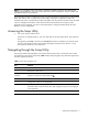
NOTE: If you repeatedly receive “Run Setup” messages, the battery located on the system board (XBAT1) may be defective. In this case, the system cannot retain configuration values in CMOS. Ask a qualified technician for assistance. The Setup Utility loads the configuration values in a battery-backed nonvolatile memory called CMOS RAM. This memory area is not part of the system RAM, which allows configuration data to be retained when power is turned off. The values take effect when the system is booted.
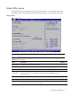
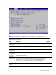
Setup Utility menus The Setup Utility menu bar displays the five primary menu selections. For detailed information and screenshots of these Setup Utility menus and their related submenus, refer to the following sections. Main Menu Figure 1 Main menu NOTE: The time is in 24-hour format. For example, 5:30 A.M. appears as 05:30:00, and 5:30, P.M. as 17:30:00. Table 2 Main menu fields Field Description Options Product Name Display the product name of the system.
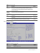
Advanced menu Figure 2 Advanced menu NOTE: The CPU Configuration setup screen varies depending on the installed processor. Table 3 Advanced menu fields Field Description CPU Configuration Configure the advanced CPU settings. IDE Configuration Configure the IDE settings. NorthBridge Configuration Configure North Bridge chipset. IPMI Configuration Configure. IPMI 2.0 settings. PCI Express Configuration Configure PCI Express settings.
Table 3 Advanced menu fields Field Description Options USB Configuration These items control various USB devices, from the USB configuration screen, press to the sub menu for the USB controller and USB 2.0 controller, use ** keys to select an item .use the and keys to change the value of the selected option. The setting is described on the following pages .the screen for the USB configuration. OnBoard Peripherals Configuration Configure the settings of onboard peripherals.
Table 4 CPU Configuration submenu fields Field Description Logical Count Display the logical count. CPU Information Select which physical CPU’s information to display. Note: Zero is always the “Boot Strap Processor” or main CPU. All others are “Application Processors”. AMD Virtualization (AMD-V) Disable AMD Virtualization. Disabled Enable AMD Virtualization. Enabled Disable the generation of ACPI_PPC, _PSS, and _PCT objects. Disabled Enable the generation of ACPI_PPC, _PSS, and _PCT objects.
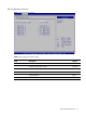
IDE Configuration submenu Figure 4 IDE Configuration submenu Table 5 IDE Configuration submenu fields Field Description Options OnChip SATA Channel Enable OnChip SATA channel. Enabled Disable OnChip SATA channel. Disabled Select Native IDE type. Native IDE Select RAID type. RAID Select AHCI type. AHCI Disable SATA controller mode.
NorthBridge Chipset Configuration submenu Figure 5 NorthBridge Chipset Configuration submenu Table 6 NorthBridge Chipset submenu fields Field Description Memory Configuration Configure memory settings. ECC Configuration Configure ECC settings. DRAM Timing Configuration Configure memory clock frequency.
IPMI Configuration submenu Figure 6 IPMI Configuration submenu Table 7 IPMI Configuration submenu fields Field Description Status of BMC Display the current status of BMC. BMC Firmware Revision Display the current revision of the BMC firmware. Options BMC/IPMI FW Date Display the date of the BMC/IPMI firmware. BMC SDR Version Display the current version of the BMC SDR. Set LAN Configuration Access the submenu to configure Option of Set LAN Configuration.
Table 7 IPMI Configuration submenu fields Field Description Options Power on the server after power loss. On Restore last state after power loss.
PCI Express Configuration submenu Figure 7 PCI Express Configuration submenu Table 8 PCI Express Configuration submenu fields Field Description Options Maximum Payload Size Set Maximum Payload of PCI Express Device or allow System BIOS select the value. Auto Set Maximum Payload of PCI Express Device or allow System BIOS select the value. 128 Bytes Set Maximum Payload of PCI Express Device or allow System BIOS select the value.
Table 8 PCI Express Configuration submenu fields Field IOMMU Mode ASPM Mode Description Options Select embedded video controller. PCI-PCIE GPP1-GPP2-GPP Select appropriate option to ensure proper AGP operation. AGP Present Disable the function of setting GART size. Disabled Set GART size in system. 32MB Set GART size in system. 64MB Set GART size in system. 128MB Set GART size in system. 256MB Set GART size in system. 512MB Set GART size in system.
Remote Access Configuration submenu Figure 8 Remote Access Configuration submenu Table 9 Remote Access Configuration submenu fields Field Description Options Remote Access Disable the Remote Access type. Disabled Enable the Remote Access type. Enabled Select Serial Port for console redirection. COM1 Serial port number Make sure the selected port is enabled. This item disappears when Remote Access is disabled. This is the default setting.
Table 9 Remote Access Configuration submenu fields Field Redirection After BIOS POST Terminal Type Description Options Select Flow Control settings for console redirection. This item disappears when Remote Access is disabled. Hardware Select Flow Control settings for console redirection. This item disappears when Remote Access is disabled. Software Turn off the redirection after POST. Disabled Redirection is active during POST and during Boot Loader. Boot Loader Redirection is always active.
Trusted Computing submenu Figure 9 Trusted Computing submenu Table 10 Trusted Computing submenu fields Field Description Options TCG/TPM Support Enable TPM TCG (TPM 1.1/1.2) support in BIOS. Yes Disable TPM TCG (TPM 1.1/1.2) support in BIOS.
USB Configuration submenu Figure 10 USB Configuration submenu Table 11 USB Configuration submenu fields Field Description Options USB BIOS Support Disable support for legacy USB. Disabled Enable support for legacy USB. Enabled Disable legacy support if no USB devices are connected.
OnBoard Peripherals Configuration submenu Figure 11 OnBoard Peripherals Configuration submenu Table 12 OnBoard Peripherals Configuration submenu fields Field Description Options Embedded NIC Port Disable onboard NIC port 1. 1 Control Disabled Enable onboard NIC port 1. Enabled Embedded NIC Port Disable onboard NIC port 1 PXE. 1 PXE Disabled Enable onboard NIC port 1 PXE. Enabled Embedded NIC Port Disable onboard NIC port 2. 2 Control Disabled Enable onboard NIC port 2.
Table 12 OnBoard Peripherals Configuration submenu fields Field Description Options Embedded NIC Port Disable onboard NIC port 4. 4 Control Disable Enable onboard NIC port 4. Enabled Embedded NIC Port Disable onboard NIC port 4 PXE. 4 PXE Disable Enable onboard NIC port 4 PXE. Enabled Allow wake up in S4/S5 over LAN. This is the default setting. Enabled Disabled Wake-On LAN in S4/S5.
Boot Menu Figure 12 Boot menu Table 13 Boot menu fields Field Description Options Boot Settings Configuration Configure settings during system boot. Boot Device Priority Use this screen to specify the order in which the system checks for a boot device. Hard Disk Drives Display HDD information if detect HDD installed. USB Device Boot Priority Force USB devices automatically showing up as top priority within their device class in the standard boot order list. This is the default setting.
Boot Settings Configuration submenu Figure 13 Boot Settings Configuration submenu Table 14 Boot Settings Configuration submenu fields Field Description Options Post Speed Up Execute the certain tests during POST. Disabled Allow BIOS to skip certain tests while booting. This is the default setting. Enabled Disable the Splash Screen function. Disabled Enable the Splash Screen function. Enabled Disable Power-on state for Numlock. Off Select Power-on state for Numlock.
Boot Device Priority submenu To change the boot order, select a boot category type such as Hard disk drives, Removable media or ATAPI CD ROM devices from the boot menu. For example, if the 1st boot device is set to Hard disk drives, then BIOS will try to boot to hard disk drives first. Figure 14 Boot Device Priority submenu NOTE: When you select a boot category from the boot menu, a list of devices in that category appears.
Hard Disk Drives submenu Figure 15 Hard Disk Drives submenu System BIOS configuration 25
Security menu Figure 16 Security menu Table 15 Security menu fields Field Description Options Supervisor Password Not installed the Supervisor password. Not Installed Installed the Supervisor password. Installed Not installed the user password. Not Installed Installed the user password. Installed User Password Change Supervisor Type the Supervisor's password in the dialogue box to set or to change Password Admin password, which allows access to the BIOS.
Table 16 Exit menu fields Field Description Options Save Changes and Exit Save the changes made and exit the BIOS Setup Utility. Discard Changes and Exit Exit the BIOS Setup utility without saving any changes you have made. Discard Changes Discard (cancel) any changes you have made. Remain in the BIOS Setup Utility. Restore Default Settings Load optimal default values for all the setup questions.
Recording custom Setup values Write down the settings from the Setup Utility and keep them in a safe place. If the custom values ever need restoring (after clearing CMOS, for example), you must run the Setup Utility and enter these custom settings again. Having a record of these custom settings makes this much easier. Loading system defaults If the system fails after you make changes in the Setup menus, reboot the server, enter Setup, and load the system default settings to correct the error.
Power-On Self Test (POST) When the server boots up, a series of tests are displayed on the screen. This is referred to as PowerOn Self-Test (POST). POST is a series of diagnostic tests that checks firmware and assemblies to ensure that the server is properly functioning. This diagnostic function automatically runs each time the server is powered on.
Table 17 POST Error Messages Error code Description 040 Refresh timer test failed 048 Password check failed 003 CMOS Battery Low 701 Insufficient Runtime space for MPS data.!!. System may operate in PIC or Non-MPS mode. 702 No enough APIC ID in range 0-0Fh can be assigned to IO APICs. (Re-assigning CPUs' local APIC ID may solve this issue) MPS Table is not built! System may operate in PIC or Non-MPS mode. 120 $A0CCMOS Cleared by Jumper.
8. Repeat steps 4 and 5. If the server now works, replace the boards and accessories one at a time to determine which one is causing the problem.
OS installation Supported OS Table 18 Supported OSes Option Description Microsoft Windows Microsoft Windows Server 2003 Standard Edition (32/64 bit) Microsoft Windows Server 2003 Enterprise Edition (32/64 bit) Microsoft Windows Server 2008 Red Hat Enterprise Linux Red Hat Enterprise Linux 5 for 32 bit and EM64T/AM D64 Red Hat Enterprise Linux 6 for 32 bit and EM64T/AM D64 SUSE Linux Enterprise Server SUSE Linux Enterprise Server 10 for 32 bit and EM64T/AM D64 SUSE Linux Enterprise Server 11 for 32 bit
BIOS update HP recommends that you update the server BIOS with the latest system BIOS version to take advantage of the most recent compatibility fixes. The latest BIOS version for your server can be downloaded from http://www.hp.com.
Server management Pre- and post-installation procedures Pre-installation procedures WARNING: Failure to properly turn off the server before you open the server or before you start removing or installing hardware components may cause serious damage as well as bodily harm. WARNING: To reduce the risk of personal injury from hot surfaces, allow the chassis and any installed hardware components to cool before touching them.
Post-installation procedures 1. Be sure all components are installed according to the described step-by-step instructions. 2. Check to make sure you have not left loose tools or parts inside the server. 3. Reinstall any expansion boards, riser board assemblies, peripherals, board covers, brackets, and system cables that you have removed. 4. Reinstall the top cover: a. Align the top cover to the chassis and then slide it towards the front panel to position it into place. b.
Index Remote Access, 16 A H Active Processor Cores, 9 Hard Disk Drives, 22 AMD Virtualization (AMD-V), 9 Hardware Health Status, 12 ASPM Mode, 15 Hardware Prefetcher, 9 Restore Default Settings, 27 B I S Basic Input/Output System, 4 IDE Configuration, 7 BIOS overview, 4 IOMMU Mode, 15 BMC Firmware Revision, 12 IPMI Configuration, 7 BMC SDR Version, 12 L BMC/IPMI FW Date, 12 Boot Device Priority, 22 Boot Settings Configuration, 22 C Change Supervisor Password, 26 Change User Password, 2