HP ProLiant SL170s G6 Server Software Configuration Guide Part number 625211-001 September 2010 (First edition)
Legal notices © Copyright 2010 Hewlett-Packard Development Company, L.P. The information contained herein is subject to change without notice. The only warranties for HP products and services are set forth in the express warranty statements accompanying such products and services. Nothing herein should be construed as constituting an additional warranty. HP shall not be liable for technical or editorial errors or omissions contained herein. Microsoft, Windows, and Windows NT are U.S.
Contents System BIOS configuration .................................................................................................................... 4 System BIOS overview ................................................................................................................................. 4 BIOS software ............................................................................................................................................ 4 BIOS Setup Utility .............................
System BIOS configuration This chapter describes the basic functions of the BIOS. System BIOS overview A Basic Input/Output System, or BIOS, is a set of programs permanently stored in an EEPROM chip (U21) located on the system board. These programs serve as an interface between the server’s hardware components and its operating system. This ProLiant server features a ROM BIOS-based diagnostic tool that monitors system activity and performs constant hardware testing to ensure proper system operation.
NOTE: If you repeatedly receive “Run Setup” messages, the battery located on the system board (XBAT1) may be defective. In this case, the system cannot retain configuration values in CMOS. Ask a qualified technician for assistance. The Setup Utility loads the configuration values in a battery-backed nonvolatile memory called CMOS RAM. This memory area is not part of the system RAM, which allows configuration data to be retained when power is turned off. The values take effect when the system is booted.
Table 1 Setup Utility navigation keys Key Function ← and → Move between selections on the menu bar. ↑ and ↓ Move the cursor to the field you want. The currently selected field is highlighted. The right side of each menu screen displays the Item Specific Help panel. This panel displays the help text for the selected field. It updates as you move the cursor to each field. <+>, <–> Select a value for the currently selected field if it is user-configurable.
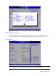
Figure 2 General Help Screen Setup Utility menus The Setup Utility menu bar displays the five primary menu selections. For detailed information and screenshots of these Setup menus and their related submenus, refer to the following sections. Main Menu Figure 3 Main Menu NOTE: The time is in 24-hour format. For example, 5:30 A.M. appears as 05:30:00, and 5:30, P.M. as 17:30:00. If you unplug the battery, setup time values will be 00:00:00.
Table 2 Main menu fields Field Description System Overview Displays the system ROM Version, the date when the Setup utility was created and identification number. Processor Displays the CPU version, speed and count. System Memory Displays the amount of system memory detected during POST. System Serial Number Displays the server serial number. The serial number is indicated on the serial number label pull tab on the front panel. Asset Tag Enter the server asset tag.
Table 3 Boot Settings Configuration submenu fields Field NUMLOCK Description Options Do not display any splash screen during POST. For HP OEM business. Disabled Set this value to allow the Number Lock on the keyboard to be enabled automatically when the computer system is boot up. This allows the immediate use of 10-keys numeric keypad located on the right side of the keyboard. To confirm this, the Number Lock LED light on the keyboard Will be lit. This is the default setting.
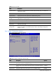
Table 4 Advanced menu fields Field Description CPU Configuration You can use this screen to select options for the CPU Configuration Settings. Use the up and down keys to select an item. Use the and keys to change the value of the selected option. A description of the selected item appears on the right side of the screen. The settings are described on the following pages. IDE Configuration You can use this screen to select options for the IDE Configuration Settings.
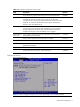
CPU Configuration submenu Figure 6 CPU Configuration submenu NOTE: Data Reuse option is for Intel®Xeon® 5600 Series Processors only. It will not display when Intel® Xeon® 5500 Series Processors are installed. Table 5 CPU Configuration submenu fields Field Description Options Data Reuse Data transfers between cache levels are optimized. Set according to observed system. It is the default value. Enabled Data transfers between cache levels are not optimized.
Table 5 CPU Configuration submenu fields Field 2DPC @1333 Intel VT-d QPI Optimization 1 GB PCI Memory Gap Description Options Provides maximum protection against failed DIMMs. Uncorrectable errors in one channel are corrected by the mirror channel. Mirrored Memory Lockstep between channel 0 and 1. Provides enhanced protection while making all installed memory available to the operating system.
IDE Configuration submenu Figure 7 IDE Configuration submenu Table 6 IDE Configuration submenu fields Field Description Options SATA Controller Mode Legacy Native mode, supports up to 4 drivers. Compatible Only available on systems with an embedded software RAID option ROM. RAID This is the DEFAULT if NCQ Mode requires that AHCI also be Enabled. Otherwise, legacy SATA Native Mode is the DEFAULT as previously specified.
Table 6 IDE Configuration submenu fields Field Description Options Set this value to stop the setup from searching the IDE bus for IDE disk drives in 20 seconds. 20 Set this value to stop the setup from searching the IDE bus for IDE disk drives in 25 seconds. 25 Set this value to stop the setup from searching the IDE bus for IDE disk drives in 30 seconds. 30 35 is the default value. It is the recommended setting when all IDE connectors are set to auto in the setup setting.
Table 7 IO Device Configuration submenu fields Option Description 2E8/IRQ3 Set this value to allow the serial port to use 2E8 as its I/O port address and IRQ 3 for the interrupt address. If the system will not use a serial device, it is best to set this port to Disabled. 2F8/IRQ3 Set this value to allow the serial port to use 2F8 as its I/O port address and IRQ 3 for the interrupt address. If the system will not use a serial device, it is best to set this port to Disabled.
Figure 10 ACPI Configuration submenu (2) Table 9 South Bridge ACPI Configuration submenu fields Field Description Options High Precision Event Enable High Precision Event Timer. This is the default setting. Timer Disable High Precision Event Timer.
IPMI Configuration submenu Figure 11 IPMI Configuration submenu Table 10 IPMI Configuration submenu fields Field Description Lite Config L-Pro This option is for 60W processors with 2X4GB DIMMs per CPU and one SATA HDD. The default setting is Disabled, when set to “Enabled”, system will load SDR for this configuration. Lite Config H-Pro This option is for 95W processors with 2X4GB DIMMs per CPU and one SATA HDD.
Figure 12 SEL Configuration submenu (1) Figure 13 SEL Configuration submenu (2) Table 11 SEL Configuration submenu fields Field Description View BMC System Event Log The option specifies BMC system event log. Select this option and press to access the submenu to view the contents of System Event log. Clear BMC System Event Log The option specifies clear system event log. If the BMC Event log is full, you can choose this item to clear out the BMC Event log.
Figure 14 Serial Port Configuration submenu Table 12 Serial Port Configuration submenu fields Field Description Options Serial Port Assignment This setting will assign the serial port connector to the system. The setting default value is System. System This setting will assign the serial port connector to the BMC (Baseboard BMC management controller). Serial Port Switching Serial Port Connection Mode This setting allows the Serial port switch between system and BMC.
Figure 15 LAN Configuration submenu Figure 16 LAN Protocol Control submenu NOTE: For “BMC NIC Allocation”: If the IPMI card is not installed, the options are “Shared” and “Disabled”, the default value is Shared. If the IPMI card is installed, the options are “Dedicated” and “Shared”, the default value is Dedicated. Table 13 LAN Configuration submenu fields Field Description Options BMC NIC Allocation Set the value support share NIC mode.
Table 13 LAN Configuration submenu fields Field Description Options Set the value support from BMC NIC allocation. Dedicated BMC LAN Configuration The option specifies DHCP (Dynamic Host Configuration Protocol) IP DHCP source. The optimal setting is Static. The setup default is DHCP. If the Static option selected is DHCP, it displays below. Current IP Address Set this value needs you manual to set the IP source. Set this value allows dynamic get the IP source.
Table 14 Watchdog Configuration submenu fields Field Description Options IPMI Watchdog Timer Disabled the items do not allow to crashes or hangs if OS crashes or hangs. Disabled Set this value to allow BMC to reset if the operating system crashes or hangs. This is the default setting. Reset System Set this value to allow BMC to Power Down if the operating system crashes or hangs. Power Down Set this value to allow BMC to Power Cycle if the operating system crashes or hangs.
Table 15 Hardware Health Information submenu fields Field Description System CPUs Health Information Display system CPUs health information. Ambient Sensors Health Information Display Ambient Sensors Health Information. DIMM Temperature Sensors Health Information Display DIMM Temperature Sensors Health Information. System Voltage Health Information Display System Voltage Health Information. System Fans Health Information Display System Fans Health Information.
Table 16 USB Configuration submenu fields Field Description Options BIOS EHCI HandOff Set this value not to support the EHCI-off. Disabled Set this value to support the EHCI-off, this is the default value. Enabled Set this value to enable USB ports, this is the default value. Enabled USB Ports Turn off external and internal USB ports. Once set, all the USB ports on M/B Disabled invalid, you can use remote KVM or clear CMOS to enable it. Phys Ports Remove remote KVM and remote Media options.
Figure 21 Remote Access Configuration submenu (2) Table 17 Remote Access Configuration submenu fields Field Description Options BIOS Serial Console Set this value to allow configuring the serial port. Enabled This value prevent you configure the serial port. It is the default value. Disabled Set this value to allow you to select 115200 as the baud rate (transmitted bits per second) of the serial port.
PCI Bus Configuration submenu Figure 22 PCI Bus Configuration submenu Table 18 PCI Bus Configuration submenu fields Field Description Options Embedded VGA Control Embedded VGA Stays ON as Primary Video Controller, regardless Always of other graphics controllers being present. Enabled Disable embedded VGA if add-in graphics controller detected. This Auto is the Default value.
Power Configuration submenu Figure 23 Power Configuration submenu (1) Figure 24 Power Configuration submenu (2) Figure 25 Power Configuration submenu (3) System BIOS configuration 27
Table 19 Power Configuration submenu fields Filed Description Options Power Efficiency Mode BIOS will initialize all power related processor and chipset settings to maximize the performance per Watt. This is the default value. Efficiency BIOS will initialize all power related processor and chipset settings to maximize the performance of the server. Performance The user has modified the configuration of power/performance related settings individually. Custom Detect the current memory speed.
Table 19 Power Configuration submenu fields Filed Description Options ASPM Mode This option would be chosen by the user if there were compatibility issues with their PCIe option cards. It is the default setting. Disabled Allows the PCIe ports to enter L0s and/or L1 states. Enabled Enable or disable the “Enabled Halt State” disallowed. when power efficiency mode is performance, value is disabled. This is the default setting.
Table 19 Power Configuration submenu fields Filed Description Options Turbo Mode Prevent processor cores to run faster than marked frequency in specific condition. When power efficiency mode is efficiency, the value is disabled. This is the default setting. Disabled Allows processor cores to run faster than marked frequency in specific condition. When performance mode is performance, the value is enabled. Enabled NOTE: Turbo Mode is currently only available on certain high-bin Intel processors.
Table 20 Boot menu fields Filed Description Options Embedded NIC Port 2 PXE Set this value not to allow boot form network. Disabled Set this value to allow boot from network. Enabled Set this value not to allow boot from network. Disabled Set this value to allow boot from network. Enabled Embedded NIC Port 1 Control Boot Device Priority Submenu To change the boot order, select a boot category type such as Hard disk drives, Removable media or ATAPI CD ROM devices from the boot menu.
Hard Disk Drives Submenu Figure 28 Hard Disk Drive submenu Security menu The Security menu allows users to set an administrator password. When entered, this password allows the user to access and change all settings in the Setup Utility.
To set an administrator password: 1. Indicates whether a supervisor password has been set, if the password has been installed, installed displays, if not, not installed displays. 2. In the Security menu screen, in the Change Admin Password field, press Enter. The Enter New Password window displays. Figure 30 Enter New Password 3. Type a new password in the Enter New Password box. The password may consist of up to six alphanumeric characters (A-Z, a-z, 0-9), then press Enter.
Figure 31 Confirm New Password 4. Type the same password in the Confirm New Password box to verify the first entry, and then press Enter. The Password Installed OK is displayed. Press OK to finish. Figure 32 Password installed 5. Press F10 to save the password and close the Setup Utility. Setup automatically changes the administrator Password. To change the Admin Password: 1. In the Security menu screen, in the Change Admin Password field, press Enter. The Enter New Password displays.
To check the administrator password: 1. In the Security menu screen, select Password Check, and then press Enter. 2. Select one of the available options and then press Enter. Figure 33 Password Check submenu Table 21 Password Check submenu fields Option Description Setup Set this value need to check password while invoking the set up utility. Always Set this value must check password while invoking setup on each boot.
Figure 34 Exit menu Table 22 Exit menu fields Option Description Save Changes and Exit Save the changes made and exit the Setup Utility. Discard Changes and Exit Discard the changes and exit the setup utility. Discard Changes Discard the changes in the utility. Load Optimal Defaults Loads the default settings for all BIOS setup fields.
ensure that the server is properly functioning. This diagnostic function automatically runs each time the server is powered on. These diagnostics, which reside in the BIOS ROM, isolate server-related logic failures and indicate the board or component that needs to be replaced, as indicated by the error messages. Most server hardware failures are accurately isolated during POST. The number of tests displayed depends on the configuration of the server.
Table 23 POST Error Messages Error Error message code Description/corrective action 010h Floppy Controller Failure The floppy controller initialized failed, the devices could not use normally 012h CMOS Date/Time Not Set The CMOS date and/or time are invalid. This error can be resolved by readjusting the system time in the Setup Utility. 048h Password check failed Password is incorrect after retried a few times. Users might need to reset the password.
Table 23 POST Error Messages Error Error message code 633h Power Supply 3 Failure or Power Supply Unplugged! Invalid or Unknown Chassis Detected! 643h Please Upgrade System BIOS or Check Hardware Configuration! 644h Power Supply 4 Failure or Power Supply Unplugged! Description/corrective action When powers supply 3 installed and power cable is not connected or the power is failed, this will appear. When Chassis ID isn’t defined, this will appear.
Table 23 POST Error Messages Error Error message code Description/corrective action 656h System Fan 4a Missing If system fan4a is not installed or failed, when the system installed non-redundant fan, it will announce this message and system will shutdown in minutes. When system installed with redundant fan, if only one fan missing, this will appear and the other fans will run at high speed. If two fans missing, this will appear and system will shutdown in minutes.
Table 23 POST Error Messages Error Error message code Description/corrective action 664h System Fan 7b Missing If system fan7b is not installed or failed, when one fan missing, system will announce this message and other fans will run at high speed. When two fans missing at the same time, this will appear and system will shutdown in minutes.
7. Insert the USB key into the system to be flashed and turn it on using the power button to flash system BIOS. 8. Upon completion, the user is notified that the BIOS Flash was successful. Remove the USB key and power cycle the system. Reprogramming the Chassis Power PIC after the FW Flash disaster If the Power PIC FW becomes corrupted, use the crisis recovery floppy or USB key to reprogram the Power PIC FW. To reprogram the Power PIC FW: 1. Perform the pre-installation procedures. 2.
OS installation Supported OSes Microsoft Windows Server Microsoft Windows Server 2008 Hyper V Red Hat Enterprise Linux (RHEL) SUSE Linux Enterprise Server (SLES) Solaris 10 for x86/x64 based Systems Citrix Essentials for XenServer (Retail) NOTE: For more information on HP's Certified and Supported ProLiant Servers for OS and Virtualization Software and latest listing of software drivers available for your server, please visit our Support Matrix at: http://www.hp.com/go/supportos.
Easy Set-up CD Instruction HP ProLiant SL170s G6 Server Easy Set-up CD is a set of software that optimizes platform configuration. 1. OS install a. Put the EZ set-up CD into CD/DVD ROM, boot from CD/DVD ROM. b. Click "Install" button. c. 2. Choose OS to install HP Insight Diagnostics Tool Basic Test a. Put the tool CD into CD/DVD ROM, boot from CD/DVD ROM. b. Run the tool following the instruction on screen.
Server management Pre- and post-installation procedures Pre-installation procedures WARNING: Failure to properly turn off the server before you open the server or before you start removing or installing hardware components may cause serious damage as well as bodily harm. WARNING: To reduce the risk of personal injury from hot surfaces, allow the chassis and any installed hardware components to cool before touching them.
To configure the BMC through the Setup Utility: 1. In the Serial Port Configuration submenu under the IPMI Configuration submenu, set the Serial port Assignment field to System or BMC. See the “Serial Port Configuration submenu fields” section for more information. 2. In the LAN Configuration Settings submenu under the IPMI configuration submenu, set the IP address, default gateway, and IP subnet mask for the BMC. You can set the addresses manually or use DHCP to set the addresses automatically. 3.
1. In the Serial Port Configuration submenu under the IPMI Configuration submenu, set the Serial port Assignment field to System or BMC. See the “Serial Port Configuration submenu fields” section for more information. 2. In the Console Redirection submenu, set Remote Access to Enable. See the “Console Redirection submenu fields” section for more information. 3. Press F10 to Save and Exit.
Index A I administrator password, 32 IDE, 14 administrator password changing, 34 IDE Configuration submenu, 13 administrator password checking, 34 IO Device Configuration submenu, 14 Advanced menu, 9 IP subnet mask, 46 asset tag, 8 IPMI Configuration submenu, 17 ATA/IDE Configuration, 13 IPMI LAN interface, 46 B L Baseboard management controller, 19 LAN Configuration, 17 Basic Input/Output System, 4 LAN Controller, 46 BIOS EHCI Hand-Off, 23 Load Option Default, 36 BIOS overview, 4 loa
Serial Port Switching, 19 system time and date setting, 4 Setup Utility menus, 7 U Share NIC Mode, 20 software, 4 Supported operating systems, 43 system configuration changing, 4 System Date, 8 USB Configuration submenu, 23 USB Controller, 23 V View BMC System Event Log, 18 system defaults, 36 W System Time, 8 Watch Dog Timer Reset, 17 Index 49