HP ProLiant SL210t Gen8 Server Maintenance and Service Guide Abstract This guide is for an experienced service technician. HP assumes you are qualified in the servicing of computer equipment and trained in recognizing hazards in products with hazardous energy levels and are familiar with weight and stability precautions for rack installations.
© Copyright 2013, 2014 Hewlett-Packard Development Company, L.P. The information contained herein is subject to change without notice. The only warranties for HP products and services are set forth in the express warranty statements accompanying such products and services. Nothing herein should be construed as constituting an additional warranty. HP shall not be liable for technical or editorial errors or omissions contained herein. Microsoft® and Windows® are U.S.
Contents Customer self repair ...................................................................................................................... 5 Parts only warranty service ............................................................................................................................ 5 Illustrated parts catalog ............................................................................................................... 15 Server components ..............................................
Node rear panel components ...................................................................................................................... 57 Node rear panel LEDs and buttons ............................................................................................................... 59 System board components .......................................................................................................................... 61 DIMM slots ......................................................
Customer self repair HP products are designed with many Customer Self Repair (CSR) parts to minimize repair time and allow for greater flexibility in performing defective parts replacement. If during the diagnosis period HP (or HP service providers or service partners) identifies that the repair can be accomplished by the use of a CSR part, HP will ship that part directly to you for replacement. There are two categories of CSR parts: • Mandatory—Parts for which customer self repair is mandatory.
Obligatoire - Pièces pour lesquelles la réparation par le client est obligatoire. Si vous demandez à HP de remplacer ces pièces, les coûts de déplacement et main d'œuvre du service vous seront facturés. Facultatif - Pièces pour lesquelles la réparation par le client est facultative. Ces pièces sont également conçues pour permettre au client d'effectuer lui-même la réparation.
In base alla disponibilità e alla località geografica, le parti CSR vengono spedite con consegna entro il giorno lavorativo seguente. La consegna nel giorno stesso o entro quattro ore è offerta con un supplemento di costo solo in alcune zone. In caso di necessità si può richiedere l'assistenza telefonica di un addetto del centro di supporto tecnico HP. Nel materiale fornito con una parte di ricambio CSR, HP specifica se il cliente deve restituire dei componenti.
defekte Teil nicht zurückschicken, kann HP Ihnen das Ersatzteil in Rechnung stellen. Im Falle von Customer Self Repair kommt HP für alle Kosten für die Lieferung und Rücksendung auf und bestimmt den Kurier-/Frachtdienst. Weitere Informationen über das HP Customer Self Repair Programm erhalten Sie von Ihrem Servicepartner vor Ort. Informationen über das CSR-Programm in Nordamerika finden Sie auf der HP Website unter (http://www.hp.com/go/selfrepair).
enviara el componente defectuoso requerido, HP podrá cobrarle por el de sustitución. En el caso de todas sustituciones que lleve a cabo el cliente, HP se hará cargo de todos los gastos de envío y devolución de componentes y escogerá la empresa de transporte que se utilice para dicho servicio. Para obtener más información acerca del programa de Reparaciones del propio cliente de HP, póngase en contacto con su proveedor de servicios local.
Neem contact op met een Service Partner voor meer informatie over het Customer Self Repair programma van HP. Informatie over Service Partners vindt u op de HP website (http://www.hp.com/go/selfrepair). Garantieservice "Parts Only" Het is mogelijk dat de HP garantie alleen de garantieservice "Parts Only" omvat. Volgens de bepalingen van de Parts Only garantieservice zal HP kosteloos vervangende onderdelen ter beschikking stellen.
No caso desse serviço, a substituição de peças CSR é obrigatória. Se desejar que a HP substitua essas peças, serão cobradas as despesas de transporte e mão-de-obra do serviço.
Customer self repair 12
Customer self repair 13
Customer self repair 14
Illustrated parts catalog Server components Item Description Spare part number Customer self repair (on page 5) 1 Processor — — a) 1.70 GHz Intel Xeon E5-2650 v2 processor, 25MB, 70 W 730250-001 Optional2 b) 1.
Item Description Spare part number Customer self repair (on page 5) c) 2.00 GHz Intel Xeon E5-2640 v2 processor, 20 MB, 95 W** 730239-001 Optional2 d) 2.10 GHz Intel Xeon E5-2620 v2 processor, 15 MB, 80 W** 730241-001 Optional2 e) 2.20 GHz Intel Xeon E5-2660 v2 processor, 25 MB, 95 W** 730237-001 Optional2 f) 2.40 GHz Intel Xeon E5-2630 v2 processor, 15 MB, 60 W** 730244-001 Optional2 g) 2.40 GHz Intel Xeon E5-2695 v2 processor, 30 MB, 115 W** 730246-001 Optional2 h) 2.
Item Description Spare part number Customer self repair (on page 5) 19 2U PCIe x16x8x8 riser* 735981-001 Mandatory1 20 2U PCIe x8x8x8 riser* 735982-001 Mandatory1 21 Cables — — a) Mini-SAS P420/P822 SFF* 735974-001 Mandatory1 b) Mini-SAS P420/822 LFF* 780130-001 Mandatory1 c) Mini-SAS P222* 735975-001 Mandatory1 d) Mini-SAS P830/P430 right-angle cable* 789128-001 Mandatory1 e) Mini-SAS P830 straight cable* 776344-001 Mandatory1 f) FBWC capacitor pack with/ cable* 660093-001
No: Kein—Einige Teile sind nicht für Customer Self Repair ausgelegt. Um den Garantieanspruch des Kunden zu erfüllen, muss das Teil von einem HP Servicepartner ersetzt werden. Im illustrierten Teilekatalog sind diese Teile mit „No“ bzw. „Nein“ gekennzeichnet. 3 Mandatory: Obligatorio—componentes para los que la reparación por parte del usuario es obligatoria.
Illustrated parts catalog 19
Removal and replacement procedures Required tools You need the following items for some procedures: • T-10 Torx screwdriver • T-15 Torx screwdriver • HP Insight Diagnostics software ("HP Insight Diagnostics" on page 53) Safety considerations Before performing service procedures, review all the safety information. Preventing electrostatic discharge To prevent damaging the system, be aware of the precautions you need to follow when setting up the system or handling parts.
This symbol on an RJ-45 receptacle indicates a network interface connection. WARNING: To reduce the risk of electric shock, fire, or damage to the equipment, do not plug telephone or telecommunications connectors into this receptacle. This symbol indicates the presence of a hot surface or hot component. If this surface is contacted, the potential for injury exists. WARNING: To reduce the risk of injury from a hot component, allow the surface to cool before touching.
If you must remove the chassis from a rack or a component from the chassis or node, then you must power down the nodes. If only one node needs to be serviced, you only need to power down that node. If you are going to service the RCM module, you must power down all nodes in the chassis. • Remove the chassis from the rack. • Remove the nodes from the chassis ("Remove the node from the chassis" on page 23).
When the node goes from the standby mode to the full power mode, the node power LED changes from amber to green. For more information about iLO, see the HP website (http://www.hp.com/go/ilo). Remove the node from the chassis CAUTION: To avoid damage to the node, always support the bottom of the node when removing it from the chassis. 1. Power down the node (on page 22). 2. Disconnect all peripheral cables from the node. 3. Remove the node from the chassis: a. Press the release button. b.
Removing a 2U node CAUTION: To avoid damage to the device, do not use the removal handle to carry it. 4. Place the node on a flat, level surface. Remove the PCI riser cage 1. Power down the node (on page 22). 2. Disconnect all peripheral cables from the node. 3. Remove the node from the chassis (on page 23). 4. (1U node only) Remove the PCI riser cage: a. Remove the screw securing the riser cage. b. Press the PCI riser cage release latch.
c. 5. Lift the PCI riser cage out of the node. (2U node only) Remove the PCI riser cage: a. If a GPU is installed, disconnect the 2U adapter cable from the GPU power cable. b. Remove the screw securing the PCI riser cage. c. Loosen the captive screw. d. Press the PCI riser cage release latch.
e. Lift the PCI riser cage out of the node. Remove the 2U adapter board bracket 1. Power down the node (on page 22). 2. Disconnect all peripheral cables from the node. 3. Remove the node from the chassis (on page 23). 4. If a GPU is installed, disconnect the 2U adapter cable from the GPU power cable. 5. Remove the 2U adapter board bracket. Remove the Mini-SAS cable 1. Power down the node (on page 22). 2. Disconnect all peripheral cables from the node.
3. Remove the node from the chassis (on page 23). 4. In a 1U node configuration: a. Remove the cable guard ("Remove the 1U cable guard" on page 27). b. Remove the 1U air baffle (on page 28). c. 5. Disconnect and remove the Mini-SAS cable. In a 2U node configuration: a. If a GPU is installed, disconnect the 2U adapter cable from the GPU power cable. b. Remove the 2U adapter board bracket (on page 26). c. Disconnect and remove the Mini-SAS cable. Remove the 1U cable guard 1.
2. Disconnect all peripheral cables from the node. 3. Remove the node from the chassis (on page 23). 4. Remove the 1U cable guard: a. Press the release latches on each side of the cable guard. b. Lift the cable guard out of the node. Remove the 1U air baffle 1. Power down the node (on page 22). 2. Disconnect all peripheral cables from the node. 3. Remove the node from the chassis (on page 23). 4. Remove the 1U cable guard (on page 27). 5. Remove the 1U air baffle.
Remove the 2U air baffle To remove the component: 1. Power down the node (on page 22). 2. Disconnect all peripheral cables from the node. 3. Remove the node from the chassis (on page 23). 4. Remove the PCI riser cage (on page 24). 5. Remove the 2U adapter board bracket (on page 26). 6. Disconnect and remove the Mini-SAS cable ("Remove the Mini-SAS cable" on page 26). 7. Remove the 2U air baffle.
o 1U PCI riser board o 2U PCI riser board To replace the component, reverse the removal procedure. FlexibleLOM riser board To remove the component: 1. Power down the node (on page 22). 2. Disconnect all peripheral cables from the node. 3. Remove the node from the chassis (on page 23). 4. In a 2U node configuration, remove the PCI riser cage (on page 24).
5. Remove the FlexibleLOM riser cage. 6. Remove the FlexibleLOM riser board from the riser cage. To replace the component, reverse the removal procedure. Adapter board To remove the component: 1. Power down the node (on page 22). 2. Disconnect all peripheral cables from the node. 3. Remove the node from the chassis (on page 23). 4. If removing the adapter board from a 1U node, go to step 8.
5. If a GPU is installed, disconnect the 2U adapter cable from the GPU power cable. 6. Remove the 2U adapter board. 7. Remove the 2U adapter board bracket (on page 26). 8. In a 1U node configuration: a. Remove the 1U cable guard (on page 27). b. Remove the 1U air baffle (on page 28). 9. Disconnect and remove the Mini-SAS cable ("Remove the Mini-SAS cable" on page 26).
10. Disconnect the power cables from the 1U adapter board. 11. Remove the 1U adapter board. To replace the component, reverse the removal procedure. DIMMs CAUTION: To prevent thermal damage, do not operate the node unless all DIMM slots are populated with either a DIMM or a DIMM blank. To remove the component: 1. Power down the node (on page 22). 2. Disconnect all peripheral cables from the node. 3. Remove the node from the chassis.
4. In a 1U node configuration: a. Remove the 1U cable guard. ("Remove the 1U cable guard" on page 27) b. Remove the 1U air baffle (on page 28). c. 5. Disconnect and remove the Mini-SAS cable ("Remove the Mini-SAS cable" on page 26). In a 2U node configuration: a. Remove the PCI riser cage (on page 24). b. Remove the 2U adapter board bracket (on page 26). c. Disconnect and remove the Mini-SAS cable ("Remove the Mini-SAS cable" on page 26). d. Remove the 2U air baffle (on page 29). 6. Remove the DIMM.
To remove the component: 1. Power down the node (on page 22). 2. Disconnect all peripheral cables from the node. 3. Remove the node from the chassis (on page 23). 4. In a 1U node configuration: a. Remove the 1U cable guard (on page 27). b. Remove the 1U air baffle (on page 28). 5. In a 2U node configuration: a. Remove the PCI riser cage (on page 24). b. Remove the 2U adapter board bracket (on page 26). c. Disconnect and remove the Mini-SAS cable ("Remove the Mini-SAS cable" on page 26). d.
8. Remove the processor from the processor retaining bracket. CAUTION: To avoid damage to the processor, do not touch the bottom of the processor, especially the contact area. To install the processor: 1. Install the processor. Verify that the processor is fully seated in the processor retaining bracket by visually inspecting the processor installation guides on either side of the processor. THE PINS ON THE SYSTEM BOARD ARE VERY FRAGILE AND EASILY DAMAGED.
CAUTION: THE PINS ON THE SYSTEM BOARD ARE VERY FRAGILE AND EASILY DAMAGED. To avoid damage to the system board, do not touch the processor or the processor socket contacts. 2. Close the processor retaining bracket. When the processor is installed properly inside the processor retaining bracket, the processor retaining bracket clears the flange on the front of the socket. CAUTION: Do not press down on the processor.
6. Install the heatsink: a. Position the heatsink on the processor backplate. b. Tighten one pair of diagonally opposite screws halfway, and then tighten the other pair of screws. c. 7. Finish the installation by completely tightening the screws in the same sequence. In a 1U node configuration: a. Install the 1U air baffle. b. Install the 1U cable guard. 8. In a 2U node configuration: a. Install the 2U air baffle. b. Connect the Mini-SAS cable. c. Install the 2U adapter board bracket. d.
5. Remove the FlexibleLOM riser cage. 6. Remove the FlexibleLOM adapter board. To replace the component, reverse the removal procedure. Expansion board To remove the component: 1. Power down the node (on page 22). 2. Disconnect all peripheral cables from the node. 3. Remove the node from the chassis (on page 23). 4. Remove the PCI riser cage (on page 24).
5. Remove the expansion board. To replace the component, reverse the removal procedure. GPU To remove the component: 1. Power down the node (on page 22). 2. Disconnect all peripheral cables from the node. 3. Remove the node from the chassis (on page 23). 4. Remove the PCI riser cage (on page 24). 5. Disconnect the GPU power cable.
6. Remove the GPU from the PCI riser cage. To replace the component, reverse the removal procedure. Heatsink To remove the component: CAUTION: The heatsink thermal interface media is not reusable and must be replaced if the heatsink is removed from the processor after it has been installed. 1. Power down the node (on page 22). 2. Disconnect all peripheral cables from the node. 3. Remove the node from the chassis (on page 23). 4. In a 1U node configuration: a.
6. Remove the heatsink. To replace the component: 1. Clean the old thermal grease from the processor with the alcohol swab. Allow the alcohol to evaporate before continuing. 2. Remove the thermal interface protective cover from the heatsink. CAUTION: Heatsink retaining screws should be tightened in diagonally opposite pairs (in an "X" pattern). 3. Install the heatsink: a. Position the heatsink on the processor backplate. b.
c. 4. Finish the installation by completely tightening the screws in the same sequence. In a 1U node configuration: a. Install the 1U air baffle. b. Install the 1U cable guard. 5. In a 2U node configuration: a. Install the 2U air baffle. b. Connect the Mini-SAS cable. c. Install the 2U adapter board bracket. d. Install the PCI riser cage. e. If a GPU is installed, connect the 2U adapter cable to the GPU power cable. 6. Install the node into the chassis. 7.
5. In a 2U node configuration: a. Remove the PCI riser cage (on page 24). b. Remove the 2U adapter board bracket (on page 26). c. Disconnect and remove the Mini-SAS cable ("Remove the Mini-SAS cable" on page 26). d. Remove the 2U air baffle (on page 29). 6. Remove the FlexibleLOM riser cage. 7. Disconnect all cables connected to the system board ("System board components" on page 61). 8. Remove all DIMMs ("DIMMs" on page 33). 9. Remove the heatsink ("Heatsink" on page 41). 10.
11. Remove the processor from the processor retaining bracket. CAUTION: To avoid damage to the processor, do not touch the bottom of the processor, especially the contact area. 12. Remove the failed system board.
To replace the system board: 1. Align the system board on the tray, and then tighten the thumbscrews to secure. 2. Open each of the processor locking levers in the order indicated, and then open the processor retaining bracket.
3. Install the processor. Verify that the processor is fully seated in the processor retaining bracket by visually inspecting the processor installation guides on either side of the processor. THE PINS ON THE SYSTEM BOARD ARE VERY FRAGILE AND EASILY DAMAGED. CAUTION: THE PINS ON THE SYSTEM BOARD ARE VERY FRAGILE AND EASILY DAMAGED. To avoid damage to the system board, do not touch the processor or the processor socket contacts. 4. Close the processor retaining bracket.
5. Press and hold the processor retaining bracket in place, and then close each processor locking lever. Press only in the area indicated on the processor retaining bracket. 6. Clean the old thermal grease from the heatsink and the top of the processor with the alcohol swab. Allow the alcohol to evaporate before continuing. 7. Apply all the grease to the top of the processor in the following pattern to ensure even distribution. 8. Install the heatsink: a.
c. Finish the installation by completely tightening the screws in the same sequence. 9. Install DIMMs. 10. Connect cables to the system board ("System board components" on page 61). 11. Install the FlexibleLOM riser cage. 12. In a 1U node configuration: a. Install the PCI riser cage. b. Install the 1U air baffle c. 13. Install the 1U cable guard. In a 2U node configuration: a. Install the 2U air baffle. b. Connect the Mini-SAS cable. c. Install the 2U adapter board bracket. d.
Warning: The serial number should ONLY be modified by qualified service personnel. This value should always match the serial number located on the chassis. 5. Press the Enter key to clear the warning. 6. Enter the serial number and press the Enter key. 7. Select Product ID. The following warning appears: Warning: The Product ID should ONLY be modified by qualified service personnel. This value should always match the Product ID on the chassis. 8. Enter the product ID and press the Enter key. 9.
7. Remove the battery. IMPORTANT: Replacing the system board battery resets the system ROM to its default configuration. After replacing the battery, reconfigure the system through RBSU. To replace the component, reverse the removal procedure. For more information about battery replacement or proper disposal, contact an authorized reseller or an authorized service provider. HP Trusted Platform Module The TPM is not a customer-removable part.
Troubleshooting Troubleshooting resources The HP ProLiant Gen8 Troubleshooting Guide, Volume I: Troubleshooting provides procedures for resolving common problems and comprehensive courses of action for fault isolation and identification, issue resolution, and software maintenance on ProLiant servers and server blades. To view the guide, select a language: • English (http://www.hp.com/support/ProLiant_TSG_v1_en) • French (http://www.hp.com/support/ProLiant_TSG_v1_fr) • Spanish (http://www.hp.
Diagnostic tools HP ROM-Based Setup Utility RBSU is a configuration utility embedded in HP ProLiant servers that performs a wide range of configuration activities that can include the following: • Configuring system devices and installed options • Enabling and disabling system features • Displaying system information • Selecting the primary boot controller • Configuring memory options • Language selection For more information on RBSU, see the HP ROM-Based Setup Utility User Guide on the HP RBSU
• From within the iLO user interface • From within HP Insight Diagnostics (on page 53) HP Insight Remote Support software HP strongly recommends that you register your device for remote support to enable enhanced delivery of your HP Warranty, HP Care Pack Service, or HP contractual support agreement.
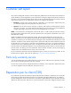
Component identification Chassis front panel components • 8-drive bay LFF drive configuration Item Description 1 Left bezel ear 2 LFF drives 3 Right bezel ear • 24-drive bay SFF drive configuration Item Description 1 Left bezel ear 2 SFF drives 3 Right bezel ear Component identification 55
Chassis front panel LEDs and buttons Item Description Status 1 Power button/LED for node 2 Green = Node 2 is powered on. Amber = Node 2 is off and has standby power. Off = Node 2 has no power. 2 Health LED for node 2 3 Power button/LED for node 1 Green = Node 1 is powered on. Amber = Node 1 is off and has standby power. Off = Node 1 has no power. 4 Health LED for node 1 Green = Node 1 is operating normally. Amber = Non-critical error has occurred. Red = Critical error has occurred.
Node rear panel components • 1U node rear panel Item Description 1 RCM module 2 Power supply 1 3 Power supply 2 4 Node 4 5 Node 3 6 Node 2 7 Node 1 • 2U node rear panel Item Description 1 RCM module 2 Power supply 1 3 Power supply 2 4 Node 3 5 Node 1 Component identification 57
• 1U node rear panel components Item Description 1 PCI slot cover 2 FlexibleLOM slot cover 3 NIC 2 port 4 NIC 1 port 5 Serial number/iLO information pull tab 6 iLO connector 7 SUV connector (1 serial/ 2 USB 2.
Item Description 7 SUV connector (1 serial/ 2 USB 2.0/ 1 video) 8 Serial connector (RJ45) Node rear panel LEDs and buttons • 1U node Item Description Status 1 Node power button/LED Green = Node is powered on. Amber = Node is off and has standby power. Off = Node has no power. 2 Health LED Green = Normal. Flashing amber = Node degraded. Flashing red = Node critical. 3 UID LED Blue = Activated. Flashing blue = Node is being managed remotely, or firmware update is in progress.
• 2U node Item Description Status 1 Node power button/LED Green = Node is powered on. Amber = Node is off and has standby power. Off = Node has no power. 2 Health LED Green = Normal. Flashing amber = Node degraded. Flashing red = Node critical. 3 UID LED Blue = Activated. Flashing blue = Node is remotely being managed, or firmware update is in progress. Off = Deactivated. 4 NIC status LED Green = Activity exists. Flashing green = Activity exists. Off = No activity exists.
System board components Item Description 1 Serial 2 connector (RJ45) 2 PCIe slot 3 TPM connector 4 System maintenance switch 5 Processor 1 6 Processor 1 DIMM slots 7 Processor 2 8 Processor 2 DIMM slots 9 RPS connector 10 Power connector 11 System battery 12 SAS connector 2 13 SAS connector 1 14 FelxibleLOM slot 15 NMI header 16 NIC connector 2 17 NIC connector 1 18 iLO connector 19 SUV connector (1 serial/ 2 USB 2.
The HP ProLiant SL210t Gen8 Server supports 2DPC using 1600 MHz DIMMs. The HP ProLiant SL210t Gen8 Server supports 1DPC using 1866 MHz DIMMs. NMI functionality An NMI crash dump creates a crash dump log before resetting a system which is not responding. Crash dump log analysis is an essential part of diagnosing reliability problems, such as failures of operating systems, device drivers, and applications.
For more information, see the HP website (http://www.hp.com/support/NMI). Drive bay numbering • Drive bay numbering for four 1U nodes In an 8-drive bay LFF drive configuration, drives are numbered from top to bottom in each box. o Drives in the first box correspond to node 1. o Drives in the second box correspond to node 2. o Drives in the third box correspond to node 3. o Drives in the fourth box correspond to node 4.
o Drives in the third and fourth box correspond to node 3. In a 24-drive bay SFF drive configuration, drives are numbered from left to right in each box. o Drives in the first box correspond to node 1. o Drives in the second box correspond to node 3. Hot-plug drive LED definitions Item LED Status Definition 1 Locate Solid blue The drive is being identified by a host application. Flashing blue The drive carrier firmware is being updated or requires an update.
Item LED Status Definition Flashing amber/green The drive is a member of one or more logical drives and predicts the drive will fail. Flashing amber The drive is not configured and predicts the drive will fail. Solid amber The drive has failed. Off The drive is not configured by a RAID controller.
Cabling Cabling overview This section provides guidelines that help you make informed decisions about cabling the server and hardware options to optimize performance. For information on cabling peripheral components, refer to the white paper on high-density deployment at the HP website (http://www.hp.com/products/servers/platforms). CAUTION: When routing cables, always be sure that the cables are not in a position where they can be pinched or crimped.
• RPS cabling FBWC capacitor pack cabling • 1U node • 2U node Cabling 67
System board Mini-SAS cabling 1U node configuration • Two LFF drives per node • Six SFF drives per node Cabling 68
2U node configuration • Four LFF drives per node • Six SFF drives per node Cabling 69
GPU power cabling PCI riser board power cabling Cabling 70
Mini-SAS P222 cabling • 1U node • 2U node with two LFF drives per node Mini-SAS P420 LFF cabling • 1U node Cabling 71
• 2U node with four LFF drives per node Mini-SAS P420 SFF cabling • 1U node • 2U node Cabling 72
o Twelve SFF drives per node o Six SFF drives per node Cabling 73
Mini-SAS P430 cabling • 1U node • 2U node o Four LFF drives per node Cabling 74
o Twelve SFF drives per node o Six SFF drives per node Cabling 75
Mini-SAS P830 cabling o 2U node with twelve SFF drives per node Cabling 76
Specifications Environmental specifications Specification Value Temperature range* — Operating 10°C to 35°C (50°F to 95°F) Shipping -40°C to 70°C (-40°F to 158°F) Maximum wet bulb temperature 28°C (82.4°F) 130 W CPU option 10°C to 25°C (50°F to 77°F) Relative humidity (noncondensing)** — Operating 10% to 90% Nonoperating 5% to 95% * All temperature ratings shown are for sea level. An altitude derating of 1°C per 300 m (1.8°F per 1,000 ft) to 3,048 m (10,000 ft) is applicable.
Hot-plug power supply calculations For hot-plug power supply specifications and calculators to determine electrical and heat loading for the server, see the HP Power Advisor website (http://www.hp.com/go/hppoweradvisor).
Acronyms and abbreviations CSR Customer Self Repair DDR double data rate DPC DIMMs per channel GPU graphics processing unit HP SIM HP Systems Insight Manager iLO Integrated Lights-Out IML Integrated Management Log LFF large form factor LOM LAN on Motherboard NMI nonmaskable interrupt RBSU ROM-Based Setup Utility RCM Rack control management Acronyms and abbreviations 79
RDIMM registered dual in-line memory module RPS redundant power supply SAS serial attached SCSI SFF small form factor SIM Systems Insight Manager UID unit identification USB universal serial bus Acronyms and abbreviations 80
Documentation feedback HP is committed to providing documentation that meets your needs. To help us improve the documentation, send any errors, suggestions, or comments to Documentation Feedback (mailto:docsfeedback@hp.com). Include the document title and part number, version number, or the URL when submitting your feedback.
Index A H adapter board 26, 31 air baffle 28, 29 heatsink 41 HP Insight Diagnostics 53 HP Insight Remote Support software 54 C Cable guard 26, 27, 66 cabling 66, 67, 68, 70 cabling, Mini-SAS option 71, 72, 74, 76 cabling, RPS 66 Care Pack 54 cautions 21 components 15, 55, 61 components, identification 15, 55 components, system board 61 CSR (customer self repair) 5 customer self repair (CSR) 5 D diagnostic tools 53 diagnostics utility 53 DIMM slot locations 61 DIMMs 33 documentation feedback 81 drive nu
ROM-Based Setup Utility (RBSU) 53 S safety information 20 SAS drives 15, 64 serial number/iLO information pull tab 57 server components 15 Smart Array controller 39 specifications, environmental 77 symbols on equipment 20 system battery 50 system board 43 system board components 61 T technical support 5 temperature requirements 77 Torx screwdriver 20 TPM (Trusted Platform Module) 51 troubleshooting 52 Trusted Platform Module (TPM) 51 U utilities 53 W warnings 21 Index 83