HP ProLiant t2500 Chassis Setup and Installation Guide Abstract This document is for the person who installs, administers, and troubleshoots servers and storage systems. HP assumes you are qualified in the servicing of computer equipment and trained in recognizing hazards in products with hazardous energy levels.
© Copyright 2013 Hewlett-Packard Development Company, L.P. The information contained herein is subject to change without notice. The only warranties for HP products and services are set forth in the express warranty statements accompanying such products and services. Nothing herein should be construed as constituting an additional warranty. HP shall not be liable for technical or editorial errors or omissions contained herein.
Contents Planning the installation ................................................................................................................. 5 Warnings and cautions .............................................................................................................................. 5 Space and airflow requirements .................................................................................................................. 6 Temperature requirements .....................................
HP 750 W CS Titanium power supply (96% efficiency) specifications .................................................. 33 HP 750 W CS Platinum Plus Hot-plug Power Supply (94% efficiency) ................................................... 33 HP 1200 W CS Platinum Plus Hot-plug Power Supply (94% efficiency) ................................................. 34 HP 1200W Common Slot 277VAC Hot Plug Power Supply (94% efficiency).........................................
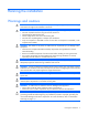
Planning the installation Warnings and cautions WARNING: To reduce the risk of personal injury or damage to equipment, heed all warnings and cautions throughout the installation instructions. WARNING: To reduce the risk of personal injury or damage to the equipment, be sure that: • • • • • The rack is bolted to the floor using the concrete anchor kit. The leveling feet extend to the floor. The full weight of the rack rests on the leveling feet. The racks are coupled together in multiple rack installations.
CAUTION: When performing non-hot-plug operations, you must power down the node and/or the system. However, it may be necessary to leave the node powered up when performing other operations, such as hot-plug installations or troubleshooting. Space and airflow requirements To enable servicing and ensure adequate airflow, observe the following spatial requirements when deciding where to install a rack: • Leave a minimum clearance of 61.0 cm (24 in) in front of the rack. • Leave a minimum clearance of 76.
covered by NFPA 70, 1999 Edition (National Electric Code) and NFPA-75, 1992 (code for Protection of Electronic Computer/Data Processing Equipment). For electrical power ratings on options, refer to the product rating label or the user documentation supplied with that option. WARNING: To reduce the risk of personal injury, fire, or damage to the equipment, do not overload the AC supply branch circuit that provides power to the rack.
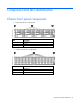
Component and LED identification Chassis front panel components • 8-drive bay LFF drive configuration Item Description 1 Left bezel ear 2 LFF drives 3 Right bezel ear • 24-drive bay SFF drive configuration Item Description 1 Left bezel ear 2 SFF drives 3 Right bezel ear Component and LED identification 8
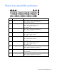
Chassis front panel LEDs and buttons Item Description Status 1 Power button/LED for node 2 Green = Node 2 is powered on. Amber = Node 2 is off and has standby power. Off = Node 2 has no power. 2 Health LED for node 2 3 Power button/LED for node 1 Green = Node 1 is powered on. Amber = Node 1 is off and has standby power. Off = Node 1 has no power. 4 Health LED for node 1 Green = Node 1 is operating normally. Amber = Non-critical error has occurred. Red = Critical error has occurred.
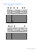
Node rear panel components • 1U node rear panel Item Description 1 RCM module 2 Power supply 1 3 Power supply 2 4 Node 4 5 Node 3 6 Node 2 7 Node 1 • 2U node rear panel Item Description 1 RCM module 2 Power supply 1 3 Power supply 2 4 Node 3 5 Node 1 Component and LED identification 10
• 1U node rear panel components Item Description 1 PCI slot cover 2 FlexibleLOM slot cover 3 NIC 2 port 4 NIC 1 port 5 Serial number/iLO information pull tab 6 iLO connector 7 SUV connector (1 serial/ 2 USB 2.
Item Description 7 SUV connector (1 serial/ 2 USB 2.0/ 1 video) 8 Serial connector (RJ45) Node rear panel LEDs and buttons • 1U node Item Description Status 1 Node power button/LED Green = Node is powered on. Amber = Node is off and has standby power. Off = Node has no power. 2 Health LED Green = Normal. Flashing amber = Node degraded. Flashing red = Node critical. 3 UID LED Blue = Activated. Flashing blue = Node is being managed remotely, or firmware update is in progress.
• 2U node Item Description Status 1 Node power button/LED Green = Node is powered on. Amber = Node is off and has standby power. Off = Node has no power. 2 Health LED Green = Normal. Flashing amber = Node degraded. Flashing red = Node critical. 3 UID LED Blue = Activated. Flashing blue = Node is remotely being managed, or firmware update is in progress. Off = Deactivated. 4 NIC status LED Green = Activity exists. Flashing green = Activity exists. Off = No activity exists.
In a 24-drive bay SFF drive configuration, drives are numbered from left to right in each box. • o Drives in the first box correspond to node 1. o Drives in the second box correspond to node 2. o Drives in the third box correspond to node 3. o Drives in the fourth box correspond to node 4. Drive bay numbering for two 2U nodes In an 8-drive bay LFF drive configuration, drives are numbered from top to bottom in each box. o Drives in the first and second box correspond to node 1.
o Drives in the second box correspond to node 3. RCM module Item Description 1 RCM module 2 RCM cable Hot-plug drive LED definitions Item LED Status Definition 1 Locate Solid blue The drive is being identified by a host application. Flashing blue The drive carrier firmware is being updated or requires an update. Rotating green Drive activity Off No drive activity Solid white Do not remove the drive. Removing the drive causes one or more of the logical drives to fail.
Item LED Status Definition 4 Drive status Solid green The drive is a member of one or more logical drives. Flashing green The drive is rebuilding or performing a RAID migration, strip size migration, capacity expansion, or logical drive extension, or is erasing. Flashing amber/green The drive is a member of one or more logical drives and predicts the drive will fail. Flashing amber The drive is not configured and predicts the drive will fail. Solid amber The drive has failed.
Setup Installation overview To set up and install the chassis: 1. Set up and install the rack. For more information, see the documentation that ships with the rack. 2. Prepare the chassis ("Preparing the chassis" on page 17). 3. Install the chassis into the rack ("Installing the chassis" on page 20). 4. Install the chassis components ("Component installation" on page 22) into the chassis. 5. Connect the chassis components ("Cabling and powering up the chassis" on page 28) in the chassis.
o Removing a 1U node o Removing a 2U node CAUTION: To avoid damage to the device, do not use the removal handle to carry it.
3. If installed, remove the security bezel. 4.
Installing the chassis WARNING: Always use at least two people to lift the chassis into the rack. If the chassis is being loaded into the rack above chest level, a third person must assist with aligning the chassis with the rails while the other two people support the weight of the chassis. WARNING: The chassis is very heavy. To reduce the risk of personal injury or damage to the equipment: • Observe local occupational health and safety requirements and guidelines for manual material handling.
Install the chassis into the rack and tighten the thumbscrews.
Component installation Installing a node into the chassis Install a node into the chassis. • 1U • 2U Installing a drive 1.
o LFF drive o SFF drive IMPORTANT: If only one drive is being installed, install it in the bay with the lowest drive number. For drive installation guidelines, see "Drive installation guidelines." CAUTION: To prevent improper cooling and thermal damage, do not operate the server unless all bays are populated with either a component or a blank. 2.
o 3. SFF drive Determine the status of the drive from the drive LED definitions ("Hot-plug drive LED definitions" on page 15). Installing the power supplies CAUTION: Do not mix power supplies with different efficiency and wattage in the chassis. Install only one type of power supply in a single chassis. Slide the power supply into the power supply bay until it clicks into place.
Installing the RCM module Install the RCM module.
Chassis options Security bezel option The security bezel helps prevent unauthorized physical access to the front panel components. Install the security bezel, and then lock it with the key provided with the kit. Node blank option Install a node blank into the chassis.
CAUTION: To prevent improper cooling and thermal damage, do not operate the HP ProLiant t2500 Chassis unless all hard drive and device bays are populated with either a component or a blank. Insert the LFF drive blank until it clicks into the chassis. SFF drive blank option CAUTION: To prevent improper cooling and thermal damage, do not operate the HP ProLiant t2500 Chassis unless all hard drive and device bays are populated with either a component or a blank.
Cabling and powering up the chassis Cabling the chassis After all system hardware is installed, cable the components. See the HP ProLiant SL Servers Site Planning Guide on the HP website (http://www.hp.com) for additional cabling and site planning requirements. WARNING: To reduce the risk of electric shock or injury due to high-current electrical energy, be sure that all power is completely disconnected at the source before beginning any power connections to the power bus bars or power bus box.
Troubleshooting Important safety information Familiarize yourself with the safety information in the following sections before troubleshooting the server. Important safety information Before servicing this product, read the Important Safety Information document provided with the server. Symbols on equipment The following symbols may be placed on equipment to indicate the presence of potentially hazardous conditions.
These symbols, on power supplies or systems, indicate that the equipment is supplied by multiple sources of power. WARNING: To reduce the risk of injury from electric shock, remove all power cords to completely disconnect power from the system.
Electrostatic discharge Preventing electrostatic discharge To prevent damaging the system, be aware of the precautions you need to follow when setting up the system or handling parts. A discharge of static electricity from a finger or other conductor may damage system boards or other static-sensitive devices. This type of damage may reduce the life expectancy of the device. To prevent electrostatic damage: • Avoid hand contact by transporting and storing products in static-safe containers.
Specifications Environmental specifications Specification Value Temperature range* Operating 10°C to 35°C (50°F to 95°F) Shipping -40°C to 70°C (-40°F to 158°F) Maximum wet bulb temperature 28°C (82.4°F) Relative humidity (noncondensing)** Operating 10% to 90% Nonoperating 5% to 95% * All temperature ratings shown are for sea level. An altitude derating of 1°C per 300 m (1.8°F per 1,000 ft) to 3,048 m (10,000 ft) is applicable. No direct sunlight allowed.
• HP 750 W Common Slot Platinum Plus Hot-plug Power Supply (94% efficiency with intelligent power discovery support) • HP 1200 W Common Slot Platinum Plus Hot-plug Power Supply (94% efficiency with intelligent power discovery support) • HP 1200W Common Slot 277VAC Hot Plug Power Supply (94% efficiency) • HP 1200W Common Slot 380VDC Hot Plug Power Supply (94% efficiency) • HP 1500W Common Slot Platinum Plus Hot-plug Power Supply (94% efficiency) CAUTION: Do not mix power supplies with different effi
Rated input current 9 A to 4.
Rated input current 6.7 A at 200 V AC 4.
5627 at 240V AC input Power supply output Rated steady-state power 1500 W at 180 to 264V AC input Maximum peak power 1500 W at 180 to 264V AC input Hot-plug power supply calculations For hot-plug power supply specifications and calculators to determine electrical and heat loading for the server, see the HP website (http://www.hp.com/go/hppoweradvisor).
Support and other resources Before you contact HP Be sure to have the following information available before you call HP: • Active Health System log (HP ProLiant Gen8 or later products) Download and have available an Active Health System log for 3 days before the failure was detected. For more information, see the HP iLO 4 User Guide or HP Intelligent Provisioning User Guide on the HP website (http://www.hp.com/go/ilo/docs).
Regulatory information Safety and regulatory compliance For safety, environmental, and regulatory information, see Safety and Compliance Information for Server, Storage, Power, Networking, and Rack Products, available at the HP website (http://www.hp.com/support/Safety-Compliance-EnterpriseProducts). Turkey RoHS material content declaration Ukraine RoHS material content declaration Warranty information HP ProLiant and X86 Servers and Options (http://www.hp.
Environmental considerations Communications interference HP system compliance tests are conducted with HP supported peripheral devices and shielded cables, such as those received with the system. The system meets interference requirements of all countries in which it is sold. These requirements provide reasonable protection against interference with radio and television communications.
• Use heel straps, toe straps, or boot straps at standing workstations. Wear the straps on both feet when standing on conductive floors or dissipating floor mats. • Use conductive field service tools. • Use a portable field service kit with a folding static-dissipating work mat. If you do not have any of the suggested equipment for proper grounding, have an authorized reseller install the part.
Acronyms and abbreviations CSR Customer Self Repair ESD electrostatic discharge IEC International Electrotechnical Commission iLO Integrated Lights-Out LFF large form factor PDU power distribution unit RCM Rack control management SFF small form factor SL-APM HP ProLiant SL Advanced Power Manager TMRA recommended ambient operating temperature UID unit identification UPS uninterruptible power system Acronyms and abbreviations 41
USB universal serial bus Acronyms and abbreviations 42
Documentation feedback HP is committed to providing documentation that meets your needs. To help us improve the documentation, send any errors, suggestions, or comments to Documentation Feedback (mailto:docsfeedback@hp.com). Include the document title and part number, version number, or the URL when submitting your feedback.
Index A G airflow requirements 5, 6 authorized reseller 37 grounding methods 31 grounding requirements 7 B H battery replacement notice 38 bezel 26 BSMI notice 38 buttons, rear panel 12 hard drive LEDs 15 hard drives, installing 22 hot-plug power supply calculations 36 HP technical support 37 HP, contacting 37 C cable configuration 28 cables, overview 28 cabling 28 calculations, power 36 Canadian notice 38 chassis options 26 components, identification 8 connectors, RCM module 15 customer self repair
power distribution unit (PDU) 7 power requirements 6, 36 power supplies 33, 34, 35 power supply LEDs 16 power supply specifications 32, 34, 35, 36 powering up the enclosure 28 preparation procedures 5 preparing the chassis 17 problem diagnosis 29 U uninterruptible power supply (UPS) 6 UPS (uninterruptible power supply) 6 R rack installation 20 rack stability 5 rack warnings 5 rear components 10 regulatory compliance identification numbers 38 regulatory compliance information 38 regulatory compliance notic