HP ProLiant SL250s Gen8 Server User Guide Abstract This document provides detailed instructions to configure and use the HP ProLiant SL250s Gen8 Server.
© Copyright 2012, 2013 Hewlett-Packard Development Company, L.P. The information contained herein is subject to change without notice. The only warranties for HP products and services are set forth in the express warranty statements accompanying such products and services. Nothing herein should be construed as constituting an additional warranty. HP shall not be liable for technical or editorial errors or omissions contained herein. Confidential computer software.
Contents Component identification ............................................................................................................... 6 Front panel components ............................................................................................................................. 6 Front panel LEDs and buttons ...................................................................................................................... 7 Rear panel components .........................................
Installing the system software .................................................................................................................... 32 Registering the server ............................................................................................................................... 33 Hardware options installation ....................................................................................................... 34 Introduction ........................................................
Intelligent Provisioning .................................................................................................................... 85 Scripting Toolkit ............................................................................................................................ 86 HP Service Pack for ProLiant ..................................................................................................................... 86 HP Smart Update Manager ...............................................
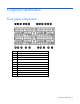
Component identification Front panel components Item Description 1 Hot-plug drive, Box 1 drive 1 2 Hot-plug drive, Box 1 drive 2 3 Option bay 1, PCI riser 4 Hot-plug drive, Box 1 drive 3 5 Hot-plug drive, Box 1 drive 4 6 Option bay 1, FlexibleLOM riser 7 SUV port 8 Serial port 9 NIC 1 network port 10 NIC 2 network port 11 iLO 4 network port Component identification 6
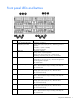
Front panel LEDs and buttons Item Description Status 1 Power On/Standby button and system power LED Solid green = System on Flashing green (1 Hz/cycle per sec) = Performing power on sequence Solid amber = System in standby Off = No power present* 2 Health LED Solid green = Normal Flashing amber = System degraded Flashing red (1 Hz/cycle per sec) = System critical Fast-flashing red (4 Hz/cycles per sec) = Power fault** 3 UID button/LED Solid blue = Activated Flashing blue (1 Hz/cycle per sec) = R
* Facility power is not present, power cord is not attached, no power supplies are installed, power supply failure has occurred, or the power button cable is disconnected. ** To identify components in a degraded or critical state, see the iLO/BIOS logs and the server troubleshooting guide.
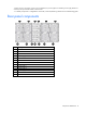
Rear panel LEDs and buttons Item Description Status 1-2, 4-7, 12-13 System fan LEDs Off = Normal Amber = Fan has failed 3 UID button/LED Solid blue = Activated Flashing blue (1 Hz/cycle per sec) = Remote management or firmware upgrade in progress Off = Deactivated 8-11 Power supply LEDs Solid green = Normal Off = One or more of the following conditions exists: • • • • Power Power Power Power is unavailable supply failed supply is in standby mode supply error System board components Component
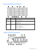
Item Description 1 Cache module connector 2 PCIe x24 riser connector 3 SATA connector 2 4 SATA connector 1 5 System battery 6 Processor socket 2 7 Processor 2 DIMM slots 8 12-pin system board power connector 9 24-pin RPS connector 10 Processor 1 DIMM slots 11 Processor socket 1 12 Mini-SAS connector 2i 13 Mini-SAS connector 1i 14 microSD card slot 15 Hot-plug drive backplane sideband connector 16 FlexibleLOM x16 riser connector 17 System maintenance switch 18 TPM connect
The arrow points to the front of the server. System maintenance switch Position Default Function S1 Off Off = iLO 4 security is enabled. On = iLO 4 security is disabled. S2 Off Off = System configuration can be changed. On = System configuration is locked. S3 Off Reserved S4 Off Reserved S5 Off Off = Power-on password is enabled. On = Power-on password is disabled. S6 Off Off = No function On = ROM reads system configuration as invalid.
CAUTION: Clearing CMOS and/or NVRAM deletes configuration information. Be sure to properly configure the server or data loss could occur. NMI functionality An NMI crash dump creates a crash dump log before resetting a system which is not responding. Crash dump log analysis is an essential part of diagnosing reliability problems, such as failures of operating systems, device drivers, and applications. Many crashes freeze a system, and the only available action for administrators is to restart the system.
• Rear SFF drive bay numbers (box 0) Hot-plug drive LED definitions Item LED Status 1 Locate Solid blue The drive is being identified by a host application. Flashing blue The drive carrier firmware is being updated or requires an update. Rotating green Drive activity Off No drive activity Solid white Do not remove the drive. Removing the drive causes one or more of the logical drives to fail. Off Removing the drive does not cause a logical drive to fail.
Item LED Status Definition Off The drive is not configured by a RAID controller.
Operations Power up the server The SL APM initiates an automatic power-up sequence when the server is installed. If the default setting is changed, use one of the following methods to power up the server: • Use a virtual power button selection through iLO 4. • Press and release the Power On/Standby button. When the server goes from the standby mode to the full power mode, the system power LED changes from amber to green.
CAUTION: To avoid damage to the server, always support the bottom of the server when removing it from the chassis. 3. Remove the server from the chassis: a. Press the release button on the front of the server, and then extend the tray handle. b. Press the release button on the side of the server. c. 4. Use the tray handle to pull the server out of the chassis. Place the server on a flat, level work surface. Remove the front GPU cage 1. Power down the server (on page 15). 2.
4. Remove the front GPU cage. Install the front GPU cage 1. Align the GPU cage with the guiding pins, and then tighten the thumbscrews.
o Right node 2. Install the server into the chassis ("Installing the server into the chassis" on page 31). 3. Connect all peripheral cables to the server. 4. Power up the server (on page 15). Remove the interposer board 1. Power down the server (on page 15). 2. Disconnect all peripheral cables from the server. 3. Remove the server from the chassis (on page 15). 4. Remove the front GPU cage (on page 16). 5. Remove the interposer board.
Install the interposer board 1. Install the interposer board. 2. Install the front GPU cage (on page 17). 3. Install the server into the chassis ("Installing the server into the chassis" on page 31). 4. Connect all peripheral cables to the server. 5. Power up the server (on page 15). Remove the front GPU bracket 1. Power down the server (on page 15). 2. Disconnect all peripheral cables from the server. 3. Remove the front GPU cage (on page 16). 4. Remove the interposer board (on page 18).
5. Remove the front GPU bracket. Install the front GPU bracket 1. Install the front GPU bracket into the server, and then tighten the thumbscrews. 2. Install the interposer board (on page 19). 3. Install the front GPU cage (on page 17). 4. Install the server into the chassis ("Installing the server into the chassis" on page 31). 5. Connect all peripheral cables to the server. 6. Power up the server (on page 15).
Remove the processor air baffle 1. Power down the server (on page 15). 2. Disconnect all peripheral cables from the server. 3. Remove the server from the chassis (on page 15). 4. Remove the front GPU cage (on page 16). 5. Remove the interposer board (on page 18). 6. Remove the front GPU bracket (on page 19). 7. Remove the processor air baffle. Install the processor air baffle 1. Install the processor air baffle.
IMPORTANT: If the DIMM latches are not fully closed, the baffle will not sit properly. 2. Install the front GPU bracket (on page 20). 3. Install the interposer board (on page 19). 4. Install the front GPU cage (on page 17). 5. Install the server into the chassis ("Installing the server into the chassis" on page 31). 6. Connect all peripheral cables to the server. 7. Power up the server (on page 15). Removing the SFF hot-plug drive cage 1. Power down the server (on page 15). 2.
Installing the SFF hot-plug drive cage 1. Install the SFF hot-plug drive cage. 2. Connect the power and Mini-SAS cables to the drive backplane. 3. Install the server into the chassis ("Installing the server into the chassis" on page 31). 4. Connect all peripheral cables to the server. 5. Power up the server (on page 15). Remove the PCI riser cage 1. Power down the server (on page 15). 2. Disconnect all peripheral cables from the server. 3. Remove the server from the chassis (on page 15). 4.
b. Lift the cage to remove it from the tray. Install the PCI riser cage 1. If necessary, install the expansion boards ("Installing an expansion board" on page 57). 2. Install the PCI riser cage. IMPORTANT: The server does not power up if the PCI riser cage is not seated properly. 3. Install the front GPU bracket (on page 20). 4. Install the interposer board (on page 19). 5. Install the front GPU cage (on page 17). 6.
8. Connect all peripheral cables to the server. 9. Power up the server (on page 15). Remove the FlexibleLOM riser cage 1. Power down the server (on page 15). 2. Disconnect all peripheral cables from the server. 3. Remove the server from the chassis (on page 15). 4. Remove the SFF hot-plug drive cage ("Removing the SFF hot-plug drive cage" on page 22). 5. Remove the front GPU cage (on page 16). 6. Remove the interposer board (on page 18). 7. Remove the front GPU bracket (on page 19). 8.
2. Install the FlexibleLOM riser cage. 3. Install the front GPU bracket (on page 20). 4. Install the interposer board (on page 19). 5. Install the front GPU cage (on page 17). 6. Install the SFF hot-plug drive cage ("Installing the SFF hot-plug drive cage" on page 23). 7. Install the server into the chassis ("Installing the server into the chassis" on page 31). 8. Connect all peripheral cables to the server. 9. Power up the server (on page 15).
Setup Optional installation services Delivered by experienced, certified engineers, HP Care Pack services help you keep your servers up and running with support packages tailored specifically for HP ProLiant systems. HP Care Packs let you integrate both hardware and software support into a single package. A number of service level options are available to meet your needs.
• Leave a minimum clearance of 63.5 cm (25 in) in front of the rack. • Leave a minimum clearance of 76.2 cm (30 in) behind the rack. • Leave a minimum clearance of 121.9 cm (48 in) from the back of the rack to the back of another rack or row of racks. HP servers draw in cool air through the front door and expel warm air through the rear door.
Power requirements Installation of this equipment must comply with local and regional electrical regulations governing the installation of information technology equipment by licensed electricians. This equipment is designed to operate in installations covered by NFPA 70, 1999 Edition (National Electric Code) and NFPA-75, 1992 (code for Protection of Electronic Computer/Data Processing Equipment).
WARNING: To reduce the risk of personal injury or damage to the equipment, be sure that: • • • • • The leveling jacks are extended to the floor. The full weight of the rack rests on the leveling jacks. The stabilizing feet are attached to the rack if it is a single-rack installation. The racks are coupled together in multiple-rack installations. Only one component is extended at a time. A rack may become unstable if more than one component is extended for any reason.
Installing the components WARNING: The server is very heavy. To reduce the risk of personal injury or damage to the equipment: • Reduce the weight of the server by removing the hard drives and power supplies before installing the server into the rack. • At least two people are required to lift the server during installation or removal. CAUTION: Always plan the rack installation so that the heaviest item is on the bottom of the rack.
5. Connect the power cord to the AC power source. WARNING: To reduce the risk of electric shock or damage to the equipment: • Do not disable the power cord grounding plug. The grounding plug is an important safety feature. • Plug the power cord into a grounded (earthed) electrical outlet that is easily accessible at all times. • Unplug the power cord from the power supply to disconnect power to the equipment. • Do not route the power cord where it can be walked on or pinched by items placed against it.
2. The first time you log into Intelligent Provisioning, follow the steps to set preferences and activate Intelligent Provisioning. 3. From the Home screen, click Perform Maintenance, and then click Firmware Update. 4. Ensure the latest drivers are available for installation. Select Intelligent Provisioning Software from the list of firmware, and click Update. If the check box is not selected, the latest drivers are already installed.
Hardware options installation Introduction If more than one option is being installed, read the installation instructions for all the hardware options and identify similar steps to streamline the installation process. WARNING: To reduce the risk of personal injury from hot surfaces, allow the drives and the internal system components to cool before touching them. CAUTION: To prevent damage to electrical components, properly ground the server before beginning any installation procedure.
CAUTION: To prevent possible server overheating, always populate processor socket 2 with a processor and a heatsink or a processor socket cover and a heatsink blank. IMPORTANT: Processor socket 1 must be populated at all times or the server does not function. 9. Open each of the processor locking levers in the order indicated, and then open the processor retaining bracket. 10. Remove the clear processor socket cover. Retain the processor socket cover for future use.
11. Install the processor. Verify that the processor is fully seated in the processor retaining bracket by visually inspecting the processor installation guides on either side of the processor. THE PINS ON THE SYSTEM BOARD ARE VERY FRAGILE AND EASILY DAMAGED. CAUTION: THE PINS ON THE SYSTEM BOARD ARE VERY FRAGILE AND EASILY DAMAGED. To avoid damage to the system board, do not touch the processor or the processor socket contacts. 12. Close the processor retaining bracket.
13. Press and hold the processor retaining bracket in place, and then close each processor locking lever. Press only in the area indicated on the processor retaining bracket. 14. Remove the thermal interface protective cover from the heatsink. CAUTION: Heatsinks specified for processor 1 and 2 are not interchangeable. Be sure to note the appropriate orientation on the heatsink label. CAUTION: Heatsink retaining screws should be tightened or loosened in diagonally opposite pairs (in an "X" pattern).
a. Position the heatsink on the processor backplate. b. Tighten one pair of diagonally opposite screws halfway, and then tighten the other pair of screws. c. Finish the installation by completely tightening the screws in the same sequence. 16. Install the processor air baffle (on page 21). 17. Install the front GPU bracket (on page 20). 18. Install the interposer board (on page 19). 19. Install the front GPU cage (on page 17). 20.
HP SmartMemory HP SmartMemory, introduced for Gen8 servers, authenticates and unlocks certain features available only on HP Qualified memory and verifies whether installed memory has passed HP qualification and test processes. Qualified memory is performance-tuned for HP ProLiant and BladeSystem servers and provides future enhanced support through HP Active Health and manageability software. Certain performance features are unique with HP SmartMemory. HP SmartMemory 1.
DIMM identification To determine DIMM characteristics, use the label attached to the DIMM and the following illustration and table. Item Description Definition 1 Size — 2 Rank 1R 2R 3R 4R 3 Data width x4 = 4-bit x8 = 8-bit 4 Voltage rating L = Low voltage (1.35V) U = Ultra low voltage (1.
is degrading. This enables DIMMs that have a higher probability of receiving an uncorrectable memory error (which results in system downtime) to be removed from operation. The server also can operate in independent channel mode or combined channel mode (Lockstep Memory mode). When running in Lockstep Memory mode, you gain reliability in one of two ways: • If running with UDIMMs (built with x8 DRAM devices), the system can survive a complete DRAM failure (SDDC).
DIMM type DIMM rank One processor Two processors RDIMM Single-rank 64GB 128 GB RDIMM Dual-rank 128 GB 256 GB UDIMM Single-rank 16 GB 32 GB UDIMM Dual-rank 64 GB 128GB LRDIMM Quad-rank 256 GB 512 GB General DIMM slot population guidelines Observe the following guidelines for all AMP modes: • Install DIMMs only if the corresponding processor is installed. • When two processors are installed, balance the DIMMs across the two processors.
• Each channel must have a valid online spare configuration. • Each channel can have a different valid online spare configuration. • Each populated channel must have a spare rank. A single dual-rank DIMM is not a valid configuration. Lockstep Memory population guidelines For Lockstep memory mode configurations, observe the following guidelines: • Observe the general DIMM slot population guidelines (on page 42). • DIMM configuration on all channels of a processor must be identical.
9. Install the DIMM. 10. Install the processor air baffle (on page 21). 11. Install the front GPU bracket (on page 20). 12. Install the interposer board (on page 19). 13. Install the front GPU cage (on page 17). 14. Install the server into the chassis ("Installing the server into the chassis" on page 31). 15. Connect all peripheral cables to the server. 16. Power up the server (on page 15).
Installing a hot-plug drive 1. Remove the drive blank. 2. Prepare the drive. 3. Install the drive. 4. Determine the status of the drive from the drive LED definitions ("Hot-plug drive LED definitions" on page 13). Installing SFF quick-release drive cages 1. Power down the server (on page 15). 2. Disconnect all peripheral cables from the server. 3. Remove the server from the chassis (on page 15). 4. Remove the front GPU cage (on page 16).
5. Remove the interposer board (on page 18). 6. Remove the front GPU bracket (on page 19). 7. Attach the Mini-SAS cable to Mini-SAS connector port 1i on the system board. 8. Attach the power connectors to the personality board. The power connectors can plug into either port on the personality board.
9. Remove the GPU blank from the cage. 10. Using the six M2.
o 11.
o Rear drive cage 12. Install the quick-release drives in the front and rear drive cages ("Installing a quick-release drive" on page 50). 13.
o Right node 14. Install the front GPU bracket (on page 20). 15. Install the interposer board (on page 19). 16. Install the front GPU cage (on page 17). 17. Install the server into the chassis ("Installing the server into the chassis" on page 31). 18. Connect all peripheral cables to the server. 19. Power up the server (on page 15). Installing a quick-release drive 1. Power down the server (on page 15). 2. Remove the server from the chassis (on page 15). 3.
5. Install the quick-release drive. 6. If removed, install the front GPU cage (on page 17). 7. Install the server into the chassis ("Installing the server into the chassis" on page 31). 8. Connect all peripheral cables to the server. 9. Power up the server (on page 15). Controller options The server ships with HP Dynamic Smart Array B320i Controller. For more information about the controller and its features, see the HP Dynamic Smart Array RAID Controller User Guide on the HP website (http://www.
CAUTION: After the server is powered down, wait 15 seconds and then check the amber LED before unplugging the cable from the cache module. If the amber LED blinks after 15 seconds, do not remove the cable from the cache module. The cache module is backing up data, and data is lost if the cable is detached. IMPORTANT: The battery pack might have a low charge when installed. In this case, a POST error message is displayed when the server is powered up, indicating that the battery pack is temporarily disabled.
10. Do one of the following: o Install the cache module in the SAS cache module connector on the system board. For connector locations, see "System board components (on page 9)." o Install the cache module into the storage controller. 11. If using a storage controller, install the controller card into the PCI riser cage ("Installing an expansion board" on page 57). 12. Install the PCI riser cage (on page 24). 13.
o Left node o Right node Hardware options installation 54
14. Install the FBWC capacitor pack into the holder mounted in the server tray. 15. Install the front GPU bracket (on page 20). 16. Install the interposer board (on page 19). 17. Install the front GPU cage (on page 17). 18. Install the SFF hot-plug drive cage ("Installing the SFF hot-plug drive cage" on page 23). 19. Install the server into the chassis ("Installing the server into the chassis" on page 31). 20. Connect all peripheral cables to the server. 21. Power up the server (on page 15).
10. Connect the Mini-SAS cable from the option kit to the storage controller. 11. Install the PCI riser cage (on page 24). 12. Install the front GPU bracket (on page 20). 13. Install the interposer board (on page 19). 14. Install the front GPU cage (on page 17). 15. Install the SFF hot-plug drive cage ("Installing the SFF hot-plug drive cage" on page 23). 16. Disconnect the existing Mini-SAS cable from the drive cage.
17. Route the Mini-SAS cable from the storage controller and connect it to the SFF hot-plug drive cage backplane. For more information see Mini-SAS cabling (on page 79). 18. Install the server into the chassis ("Installing the server into the chassis" on page 31). 19. Connect all peripheral cables to the server. 20. Power up the server (on page 15). Expansion board options Installing an expansion board 1. Power down the server (on page 15). 2. Remove the server from the chassis (on page 15). 3.
9. Install the expansion board into the slot until it seats firmly. 10. Install the PCI riser cage (on page 24). IMPORTANT: The server does not power up if the PCI riser cage is not seated properly. 11. Connect any required internal cables to the expansion board. Refer to the documentation that ships with the expansion board. 12. Install the front GPU bracket (on page 20). 13. Install the interposer board (on page 19). 14. Install the front GPU cage (on page 17). 15.
GPU installation Large BAR setting for GPU installation The system maintenance switch position 9 controls the PCIe 64-bit BAR (large BAR) function.
GPU population rules Observe the following population rules when installing a GPU in the server: CAUTION: For proper cooling, be sure that all slots in the GPU cage are occupied by a GPU or a GPU blank.
b. Remove the GPU blank from the cage. 5. To install the GPU in the rear GPU cage: a. Remove the interposer board (on page 18). b. Remove the rear GPU cage. 6. Remove the GPU cage standoffs: o When installing the Tesla K20/K20X GPUs, remove the three standoffs. o When installing the Tesla K10 and GRID K2 GPUs, remove the two rear standoffs. Do not remove the single standoff on the front of the cage.
— Front GPU cage — Rear GPU cage 7. Remove the existing front I/O bracket from the GPU. 8.
Use the M2.5 screws to attach this bracket.
9. Connect the power and power capping cable to the GPU. 10.
— Rear GPU cage o Tesla K20/K20X GPUs — Front GPU cage — Rear GPU cage Hardware options installation 65
To install a secondary GPU in the rear cage: a. Install the GPU cage divider plate included in the original server box. b.
— Tesla K20/K20X GPUs 11. Install the GPU cage. 12. Install the interposer board (on page 19). 13. Install the front GPU cage (on page 17). 14. Install the server into the chassis ("Installing the server into the chassis" on page 31). 15. Connect all peripheral cables to the server. 16. Power up the server (on page 15). Connecting the SUV cable CAUTION: Before disconnecting the SUV cable from the connector, always squeeze the release buttons on the sides of the connector.
Item Connector Description 3 Video For connecting a video monitor 4 USB For connecting up to two USB devices 5 Serial For trained personnel to connect a null modem serial cable and perform advanced diagnostic procedures server front panel Redundant hot-plug power supply option CAUTION: All power supplies installed in the server must have the same output power capacity. Verify that all power supplies have the same part number and label color.
3. Remove the protective cover from the connector pins on the power supply. WARNING: To reduce the risk of electric shock or damage to the equipment, do not connect the power cord to the power supply until the power supply is installed. 4. Install the redundant power supply into the bay until it clicks. 5. Connect the power cord to the power supply.
6. Use the strain relief clip from the server hardware kit to secure the power cord. 7. Route the power cord through the cable management solution. 8. Connect the power cord to the power source. 9. Be sure that the power supply LED is green. HP Trusted Platform Module option For more information about product features, specifications, options, configurations, and compatibility, see the product QuickSpecs on the HP Product Bulletin website (http://www.hp.com/go/productbulletin).
• When returning a system board for service replacement, do not remove the TPM from the system board. When requested, HP Service provides a TPM with the spare system board. • Any attempt to remove an installed TPM from the system board breaks or disfigures the TPM security rivet. Upon locating a broken or disfigured rivet on an installed TPM, administrators should consider the system compromised and take appropriate measures to ensure the integrity of the system data.
8. Install the TPM board. Press down on the connector to seat the board ("System board components" on page 9). 9. Install the TPM security rivet by pressing the rivet firmly into the system board. 10. Install the FlexibleLOM riser cage (on page 25). 11. Install the SFF hot-plug drive cage ("Installing the SFF hot-plug drive cage" on page 23). 12. Install the front GPU bracket (on page 20). 13. Install the interposer board (on page 19). 14. Install the front GPU cage (on page 17). 15.
key/password is required to enter Recovery Mode after BitLocker™ detects a possible compromise of system integrity. To help ensure maximum security, observe the following guidelines when retaining the recovery key/password: • Always store the recovery key/password in multiple locations. • Always store copies of the recovery key/password away from the server. • Do not save the recovery key/password on the encrypted hard drive. Enabling the Trusted Platform Module 1.
Cabling Cabling overview This section provides guidelines that help you make informed decisions about cabling the server and hardware options to optimize performance. For information on cabling peripheral components, refer to the white paper on high-density deployment at the HP website (http://www.hp.com/products/servers/platforms). CAUTION: When routing cables, always be sure that the cables are not in a position where they can be pinched or crimped.
SFF hot-plug drive cage Front quick-release cage • Left node Cabling 75
• Right node Rear quick-release drive cage • Left node Cabling 76
• Right node Front GPU • Left node Item Description 1 Front GPU riser board to L2 power board 2 Front GPU to front GPU riser board Cabling 77
• Right node Item Description 1 Front GPU riser board to L2 power board 2 Front GPU to front GPU riser board Rear GPU Item Description 1 Rear GPU riser board to L2 power board 2 Rear GPU to rear GPU riser board Cabling 78
Mini-SAS cabling SFF hot-plug drive cage Front quick-release drive cage • Left node Cabling 79
• Right node Rear quick-release drive cage • Left node Cabling 80
• Right node FBWC capacitor pack cabling • Left node Cabling 81
• Right node Cabling 82
Software and configuration utilities Server mode The software and configuration utilities presented in this section operate in online mode, offline mode, or in both modes.
iLO 4 enables and manages the Active Health System (on page 84) and also features Agentless Management. All key internal subsystems are monitored by iLO 4. SNMP alerts are sent directly by iLO 4 regardless of the host operating system or even if no host operating system is installed. HP Insight Remote Support software is also available in HP iLO with no operating system software, drivers, or agents.
The Active Health System log, in conjunction with the system monitoring provided by Agentless Management or SNMP Pass-thru, provides continuous monitoring of hardware and configuration changes, system status, and service alerts for various server components. The Agentless Management Service is available in the SPP, which is a disk image (.iso) that you can download from the HP website (http://www.hp.com/go/spp/download).
This functionality supports operating systems that are supported by the server. For operating systems supported by the server, see the HP website (http://www.hp.com/go/supportos). If a significant change occurs between data-gathering intervals, the survey function marks the previous information and overwrites the survey data files to reflect the latest changes in the configuration.
SPP has several key features for updating HP ProLiant servers. Using HP SUM as the deployment tool, SPP can be used in an online mode on a Windows or Linux hosted operating system, or in an offline mode where the server is booted to the ISO so that the server can be updated automatically with no user interaction or updated in interactive mode. For more information or to download SPP, see the HP website (http://www.hp.com/go/spp).
For more information on RBSU, see the HP ROM-Based Setup Utility User Guide on the Documentation CD or the HP website (http://www.hp.com/support/rbsu). Using RBSU To use RBSU, use the following keys: • To access RBSU, press the F9 key during power-up when prompted. • To navigate the menu system, use the arrow keys. • To make selections, press the Enter key. • To access Help for a highlighted configuration option, press the F1 key.
Boot options Near the end of the boot process, the boot options screen is displayed. This screen is visible for several seconds before the system attempts to boot from a supported boot device. During this time, you can do the following: • Access RBSU by pressing the F9 key. • Access Intelligent Provisioning Maintenance Menu by pressing the F10 key. • Access the boot menu by pressing the F11 key. • Force a PXE Network boot by pressing the F12 key.
10. Press the Esc key to exit RBSU. 11. Press the F10 key to confirm exiting RBSU. The server automatically reboots.
Option ROM Configuration for Arrays Before installing an operating system, you can use the ORCA utility to create the first logical drive, assign RAID levels, and establish online spare configurations.
Legacy USB support provides USB functionality in environments where USB support is not available normally. Specifically, HP provides legacy USB functionality for the following: • POST • RBSU • Diagnostics • DOS • Operating environments which do not provide native USB support Redundant ROM support The server enables you to upgrade or configure the ROM safely with redundant ROM support. The server has a single ROM that acts as two separate ROM images.
Software and firmware Software and firmware should be updated before using the server for the first time, unless any installed software or components require an older version. For system software and firmware updates, download the SPP ("HP Service Pack for ProLiant" on page 86) from the HP website (http://www.hp.com/go/spp). Version control The VCRM and VCA are web-enabled Insight Management Agents tools that HP SIM uses to schedule software update tasks to the entire enterprise.
For more information, see one of the following websites: • HP ProLiant Server Services website (http://www.hp.com/services/proliant) • HP BladeSystem Services website (http://www.hp.com/services/bladesystem) Change control and proactive notification HP offers Change Control and Proactive Notification to notify customers 30 to 60 days in advance of upcoming hardware and software changes on HP commercial products. For more information, refer to the HP website (http://www.hp.com/go/pcn).
Troubleshooting Troubleshooting resources The HP ProLiant Gen8 Troubleshooting Guide, Volume I: Troubleshooting provides procedures for resolving common problems and comprehensive courses of action for fault isolation and identification, issue resolution, and software maintenance on ProLiant servers and server blades. To view the guide, select a language: • English (http://www.hp.com/support/ProLiant_TSG_v1_en) • French (http://www.hp.com/support/ProLiant_TSG_v1_fr) • Spanish (http://www.hp.
3. Remove the server from the chassis (on page 15). 4. Remove the front GPU cage (on page 16). 5. Remove the front GPU bracket (on page 19). 6. Remove the PCI riser cage (on page 23). 7. Locate the battery on the system board ("System board components" on page 9). 8. Remove the battery. IMPORTANT: Replacing the system board battery resets the system ROM to its default configuration. After replacing the battery, reconfigure the system through RBSU.
Regulatory information Safety and regulatory compliance For safety, environmental, and regulatory information, see Safety and Compliance Information for Server, Storage, Power, Networking, and Rack Products, available at the HP website (http://www.hp.com/support/Safety-Compliance-EnterpriseProducts). Belarus Kazakhstan Russia marking Turkey RoHS material content declaration Ukraine RoHS material content declaration Warranty information HP ProLiant and X86 Servers and Options (http://www.hp.
Electrostatic discharge Preventing electrostatic discharge To prevent damaging the system, be aware of the precautions you need to follow when setting up the system or handling parts. A discharge of static electricity from a finger or other conductor may damage system boards or other static-sensitive devices. This type of damage may reduce the life expectancy of the device. To prevent electrostatic damage: • Avoid hand contact by transporting and storing products in static-safe containers.
Specifications Environmental specifications Specification Value Temperature range* — Operating 10°C to 35°C (50°F to 95°F) Shipping -40°C to 70°C (-40°F to 158°F) Maximum wet bulb temperature 28°C (82.4°F) 130 W CPU option 10°C to 25°C (50°F to 77°F) Relative humidity (noncondensing)** — Operating 10% to 90% Nonoperating 5% to 95% * All temperature ratings shown are for sea level. An altitude derating of 1°C per 300 m (1.8°F per 1,000 ft) to 3,048 m (10,000 ft) is applicable.
Support and other resources Before you contact HP Be sure to have the following information available before you call HP: • Active Health System log (HP ProLiant Gen8 or later products) Download and have available an Active Health System log for 3 days before the failure was detected. For more information, see the HP iLO 4 User Guide or HP Intelligent Provisioning User Guide on the HP website (http://www.hp.com/go/ilo/docs).
providers or service partners) identifies that the repair can be accomplished by the use of a CSR part, HP will ship that part directly to you for replacement. There are two categories of CSR parts: • Mandatory—Parts for which customer self repair is mandatory. If you request HP to replace these parts, you will be charged for the travel and labor costs of this service. • Optional—Parts for which customer self repair is optional. These parts are also designed for customer self repair.
Pour plus d'informations sur le programme CSR de HP, contactez votre Mainteneur Agrée local. Pour plus d'informations sur ce programme en Amérique du Nord, consultez le site Web HP (http://www.hp.com/go/selfrepair). Riparazione da parte del cliente Per abbreviare i tempi di riparazione e garantire una maggiore flessibilità nella sostituzione di parti difettose, i prodotti HP sono realizzati con numerosi componenti che possono essere riparati direttamente dal cliente (CSR, Customer Self Repair).
HINWEIS: Einige Teile sind nicht für Customer Self Repair ausgelegt. Um den Garantieanspruch des Kunden zu erfüllen, muss das Teil von einem HP Servicepartner ersetzt werden. Im illustrierten Teilekatalog sind diese Teile mit „No“ bzw. „Nein“ gekennzeichnet. CSR-Teile werden abhängig von der Verfügbarkeit und vom Lieferziel am folgenden Geschäftstag geliefert. Für bestimmte Standorte ist eine Lieferung am selben Tag oder innerhalb von vier Stunden gegen einen Aufpreis verfügbar.
sustituciones que lleve a cabo el cliente, HP se hará cargo de todos los gastos de envío y devolución de componentes y escogerá la empresa de transporte que se utilice para dicho servicio. Para obtener más información acerca del programa de Reparaciones del propio cliente de HP, póngase en contacto con su proveedor de servicios local. Si está interesado en el programa para Norteamérica, visite la página web de HP siguiente (http://www.hp.com/go/selfrepair).
Opcional – Peças cujo reparo feito pelo cliente é opcional. Essas peças também são projetadas para o reparo feito pelo cliente. No entanto, se desejar que a HP as substitua, pode haver ou não a cobrança de taxa adicional, dependendo do tipo de serviço de garantia destinado ao produto. OBSERVAÇÃO: Algumas peças da HP não são projetadas para o reparo feito pelo cliente. A fim de cumprir a garantia do cliente, a HP exige que um técnico autorizado substitua a peça.
Support and other resources 106
Support and other resources 107
Acronyms and abbreviations ABEND abnormal end ACU Array Configuration Utility ADM Advanced Data Mirroring AMP Advanced Memory Protection ASR Automatic Server Recovery BAR base address register BMC baseboard management controller CSA Canadian Standards Association CSR Customer Self Repair DDDC Double Device Data Correction DDR double data rate ESD electrostatic discharge Acronyms and abbreviations 108
FBWC flash-backed write cache GPU graphics processing unit HDD hard drive HP SIM HP Systems Insight Manager HP SUM HP Smart Update Manager IEC International Electrotechnical Commission iLO Integrated Lights-Out IML Integrated Management Log ISO International Organization for Standardization LFF large form factor LOM LAN on Motherboard LRDIMM load reduced dual in-line memory module NMI nonmaskable interrupt NVRAM nonvolatile memory Acronyms and abbreviations 109
OA Onboard Administrator ORCA Option ROM Configuration for Arrays PCIe Peripheral Component Interconnect Express PCI-X peripheral component interconnect extended POST Power-On Self Test RBSU ROM-Based Setup Utility RDIMM registered dual in-line memory module RDP Rapid Deployment Pack RPS redundant power supply SAS serial attached SCSI SATA serial ATA SDDC Single Device Data Correction SFF small form factor SIM Systems Insight Manager Acronyms and abbreviations 110
SLAPM SL Advanced Power Manager SPP HP Service Pack for ProLiant SSD solid-state drive SUV serial, USB, video TMRA recommended ambient operating temperature TPM Trusted Platform Module UDIMM unregistered dual in-line memory module UID unit identification USB universal serial bus VCA Version Control Agent VCRM Version Control Repository Manager Acronyms and abbreviations 111
Documentation feedback HP is committed to providing documentation that meets your needs. To help us improve the documentation, send any errors, suggestions, or comments to Documentation Feedback (mailto:docsfeedback@hp.com). Include the document title and part number, version number, or the URL when submitting your feedback.
Index A ACU (Array Configuration Utility) Advanced ECC memory 41, 42, airflow requirements 27, 28 Array Configuration Utility (ACU) ASR (Automatic Server Recovery) authorized reseller 100 auto-configuration process 88 Automatic Server Recovery (ASR) 83, 90 89 90 91 91 B BIOS upgrade 83, 91 boot options 32, 89 BSMI notice 97 buttons 6, 8, 9 C cables 74 cabling 55, 67, 74, 77, 81 cabling, drive cage 75, 79, 80 cabling, quick-release drive cage 79, 80 cabling, storage system 79 Care Pack 27, 93 Change Cont
grounding methods 98 grounding requirements 29 H hard drive LEDs 13 hard drives, determining status of 13 hardware options 34 hardware options installation 34 health driver 91 health LEDs 7 hot-plug drive, installing 45 HP Insight Diagnostics 85 HP SmartMemory 39 I iLO (Integrated Lights-Out) 83, 84, 85 iLO connector 6 IML (Integrated Management Log) 83, 85 Insight Diagnostics 85, 92 installation services 27 installation, server options 34 installing hardware 34 installing server into chassis 31 Integrate
rear components 8 rear panel components 8 rear panel connectors 8 rear panel LEDs 9 redundant power supply 68 redundant ROM 92 registering the server 33 regulatory compliance notices 97 removing server from chassis 15 requirements, airflow 27 requirements, power 29, 99 requirements, space 27 requirements, temperature 28 riser board cabling 78 ROM redundancy 92 ROM-Based Setup Utility (RBSU) 73, 87 ROMPaq utility 83, 91, 92 S safety considerations 29, 92, 97, 98 safety information 92, 97 SAS cabling 55, 79