HP ProLiant SL390s G7 1U Half-width Server Installation Instructions Part Number 614092-003 March 2013 (Third Edition)
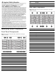
Item Description 11 iLO 3 network port 12 UID LED/SW Rear Panel Components Figure 2 Rear panel components of the s6500 chassis with eight SL390s 1U servers Identifying Server Components Item Description Front Panel Components 1 Power supply 1 2 Power supply 2 Figure 1 Front panel components of the s6500 chassis with eight SL390s 1U servers 3 Power supply 3 4 Power supply 4 5 UID LED 6 APM connector 7 Fan 1 8 Fan 2 9 Fan 3 10 Fan 4 11 Fan 5 12 Fan 6 13 Fan 7 14 Fan 8 I
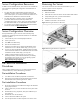
Server Configuration Resources Removing the Server In addition to this Installation Sheet, other resources are available for more information regarding the configuration and maintenance of your server: You need to remove the server from the chassis before you can remove or replace a server component.
Installing the Hard Disk Drive Figure 6 DIMM slot population sequence Each chassis can accommodate eight 1U server trays. Each server tray can accommodate two LFF or four SFF hard disk drives for a maximum of 16 LFF or 32 SFF hard disk drives per chassis. This server supports both SAS and SATA hard disk drives and SSDs. CAUTION: Drives can be damaged by static electricity. Before handling drives, touch an unpainted metal surface to discharge static electricity. To install an LFF hard disk drive: 1.
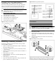
Installing a Processor Figure 9 Reinserting a processor The HP ProLiant SL390s G7 1U Half-width Server supports Intel Nehalem and Westmere Processors High Wattage 130W,95W,80W (Dual CPUs 64-bit), and Nehalem Processors Low Wattage 60W and Westmere Processor Low Wattage 40W(Dual CPUs 64-bit). NOTE: If one processor is being installed, it should be installed in the socket furthest from the IOH/chipset.
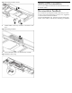
Figure 11 Removing the processor installation tool 5. Figure 13 Installing the heatsink IMPORTANT: If the heatsink has been removed for any reason, it is critical that you apply more thermal interface material to the integrated heat spreader on the processor to ensure proper thermal bonding between the processor and the heatsink. Clean the contact surface of both the processor and heatsink with an alcohol pad, then re-apply an HPapproved thermal interface material before reinstalling the processor.
Figure 15 Installing the BBWC bracket Additional Documentation You can access additional information and documentation from the HP external website. Documentation Feedback HP is committed to providing documentation that meets your needs. To help us improve the documentation, send any errors, suggestions, or comments to Documentation Feedback (mailto:docsfeedback@hp.com). Include the document title and part number, version number, or the URL when submitting your feedback. 3.
Legal notices © Copyright 2010, 2013 Hewlett-Packard Development Company, L.P. The information contained herein is subject to change without notice. The only warranties for HP products and services are set forth in the express warranty statements accompanying such products and services. Nothing herein should be construed as constituting an additional warranty. HP shall not be liable for technical or editorial errors or omissions contained herein.