HP ProLiant SL390s G7 1U Half-width Server Maintenance and Service Guide Part number 614098-004 Fourth edition March 2013
Legal notices © Copyright 2010, 2013 Hewlett-Packard Development Company, L.P. The information contained herein is subject to change without notice. The only warranties for HP products and services are set forth in the express warranty statements accompanying such products and services. Nothing herein should be construed as constituting an additional warranty. HP shall not be liable for technical or editorial errors or omissions contained herein. Microsoft® and Windows® are U.S.
Contents Customer self repair ............................................................................................................................... 5 Parts only warranty service ........................................................................................................................ 5 Illustrated parts catalog ......................................................................................................................... 16 Mechanical components ...........................
HP Insight Remote Support software ......................................................................................................... 72 USB support and functionality .................................................................................................................. 73 USB support ..................................................................................................................................... 73 Internal USB functionality ............................................
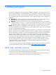
Customer self repair HP products are designed with many Customer Self Repair (CSR) parts to minimize repair time and allow for greater flexibility in performing defective parts replacement. If during the diagnosis period HP (or HP service providers or service partners) identifies that the repair can be accomplished by the use of a CSR part, HP will ship that part directly to you for replacement. There are two categories of CSR parts: • Mandatory—Parts for which customer self repair is mandatory.
Réparation par le client (CSR) Les produits HP comportent de nombreuses pièces CSR (Customer Self Repair = réparation par le client) afin de minimiser les délais de réparation et faciliter le remplacement des pièces défectueuses. Si pendant la période de diagnostic, HP (ou ses partenaires ou mainteneurs agréés) détermine que la réparation peut être effectuée à l'aide d'une pièce CSR, HP vous l'envoie directement.
Riparazione da parte del cliente Per abbreviare i tempi di riparazione e garantire una maggiore flessibilità nella sostituzione di parti difettose, i prodotti HP sono realizzati con numerosi componenti che possono essere riparati direttamente dal cliente (CSR, Customer Self Repair). Se in fase di diagnostica HP (o un centro di servizi o di assistenza HP) identifica il guasto come riparabile mediante un ricambio CSR, HP lo spedirà direttamente al cliente per la sostituzione.
Customer Self Repair HP Produkte enthalten viele CSR-Teile (Customer Self Repair), um Reparaturzeiten zu minimieren und höhere Flexibilität beim Austausch defekter Bauteile zu ermöglichen. Wenn HP (oder ein HP Servicepartner) bei der Diagnose feststellt, dass das Produkt mithilfe eines CSR-Teils repariert werden kann, sendet Ihnen HP dieses Bauteil zum Austausch direkt zu.
Reparaciones del propio cliente Los productos de HP incluyen muchos componentes que el propio usuario puede reemplazar (Customer Self Repair, CSR) para minimizar el tiempo de reparación y ofrecer una mayor flexibilidad a la hora de realizar sustituciones de componentes defectuosos.
Customer Self Repair Veel onderdelen in HP producten zijn door de klant zelf te repareren, waardoor de reparatieduur tot een minimum beperkt kan blijven en de flexibiliteit in het vervangen van defecte onderdelen groter is. Deze onderdelen worden CSR-onderdelen (Customer Self Repair) genoemd.
Reparo feito pelo cliente Os produtos da HP são projetados com muitas peças para reparo feito pelo cliente (CSR) de modo a minimizar o tempo de reparo e permitir maior flexibilidade na substituição de peças com defeito. Se, durante o período de diagnóstico, a HP (ou fornecedores/parceiros de serviço da HP) concluir que o reparo pode ser efetuado pelo uso de uma peça CSR, a peça de reposição será enviada diretamente ao cliente.
/Customer self repair 12
/Customer self repair 13
/Customer self repair 14
/Customer self repair 15
Illustrated parts catalog Mechanical components Item Description Spare part number Customer self repair 1 s6500 4U chassis — — 2 1U left tray — — 3 Left front I/O bezel — — 4 Right front I/O bezel — — 5 1U right tray — — 6 Power supply top cover — — Mandatory—Parts for which customer self repair is mandatory. If you request HP to replace these parts, you will be charged for the travel and labor costs of this service. 1 Optional—Parts for which customer self repair is optional.
No—Some HP parts are not designed for customer self repair. In order to satisfy the customer warranty, HP requires that an authorized service provider replace the part. These parts are identified as “No” in the Illustrated Parts Catalog. 3 Mandatory : Obligatoire—Pièces pour lesquelles la réparation par le client est obligatoire. Si vous demandez à HP de remplacer ces pièces, les coûts de déplacement et main d’œuvre du service vous seront facturés.
embargo, si precisa que HP realice su sustitución, puede o no conllevar costes adicionales, dependiendo del tipo de servicio de garantía correspondiente al producto. No: No—Algunos componentes no están diseñados para que puedan ser reparados por el usuario. Para que el usuario haga valer su garantía, HP pone como condición que un proveedor de servicios autorizado realice la sustitución de estos componentes. Dichos componentes se identifican con la palabra “No” en el catálogo ilustrado de componentes.
Illustrated parts catalog 19
System components Item Description Spare part number Customer self repair 1 System board 620753-001 Optional2 2 PCIe x24 card 600676-001 Optional2 3 PCIe x16 riser card 536654-001 Optional2 4 Drive options — — Hard drive, SATA 160GB 7.2K LFF 574269-001 Optional2 Hard drive, SATA 500GB 7.2K LFF 574270-001 Optional2 Hard drive, SATA 1TB 7.
Item 5 6 Description Spare part number Customer self repair Hard drive, SATA 160GB 7.2K SFF 575053-001 Optional2 Hard drive, SATA 500GB 7.
Item Description Spare part number Customer self repair Processor Intel L5640 2.26GHz/1333/12M/6c/5.86 QPI/60W 594890-001 Optional2 Processor Intel L5630 2.13GHz/1066/12M/4c/5.86 QPI/40W 594891-001 Optional2 Processor Intel ZX5690 638136-001 Optional2 Processor Intel ZX5687 3.60GHz/1333/12M/4c/6.
Item Description Spare part number Customer self repair 14 RPS cable, right 621292-001 Optional RPS cable, left 621293-001 Optional Power converter internal cable, right 602115-001 Optional Power converter internal cable, left 602114-001 Optional System board power cable, right 621294-001 Optional System board power cable, left 621295-001 Optional 17 Fan 1 power/signal cable 600670-001 Optional 18 RCM enablement cable 622068-001 Optional RDM cable 623164-001 Optional2 Health
effectué par un Mainteneur Agréé. Ces pièces sont identifiées par la mention “Non” dans le Catalogue illustré. Mandatory: Obbligatorie—Parti che devono essere necessariamente riparate dal cliente. Se il cliente ne affida la riparazione ad HP, deve sostenere le spese di spedizione e di manodopera per il servizio. 1 Optional: Opzionali—Parti la cui riparazione da parte del cliente è facoltativa. Si tratta comunque di componenti progettati per questo scopo.
No: Nee—Sommige HP onderdelen zijn niet ontwikkeld voor reparatie door de klant. In verband met de garantievoorwaarden moet het onderdeel door een geautoriseerde Service Partner worden vervangen. Deze onderdelen worden in de geïllustreerde onderdelencatalogus aangemerkt met "Nee". 3 Mandatory: Obrigatória—Peças cujo reparo feito pelo cliente é obrigatório. Se desejar que a HP substitua essas peças, serão cobradas as despesas de transporte e mão-de-obra do serviço.
HP contact information For United States and worldwide contact information, see the Contact HP website at http://hp.com/go/assistance. In the United States: • To contact HP by phone, call 1-800-334-5144. For continuous quality improvement, calls may be recorded or monitored. • If you have purchased a Care Pack (service upgrade), see the Support & Drivers website at http://www8.hp.com/us/en/support-drivers.html. If the problem cannot be resolved at the website, call 1-800-633-3600.
Removal and replacement procedures This chapter provides subassembly/module-level removal and replacement procedures for the HP ProLiant SL390s G7 1U Half-width Server. Review the specifications of a new component before installing it to make sure it is compatible with the server. When you integrate new components into the system, record its model and serial number, and any other pertinent information for future reference.
• Use conductive field service tools. Pre-installation procedure Perform the steps below before you open the server or before you remove or replace any component. WARNING: Failure to properly turn off the server before you open the server or before your start installing/removing components may cause serious damage as well as bodily harm. 1. Turn off the server and all the peripherals connected to it. 2.
CAUTION: Do not operate the server for long periods with the access panel open or removed. Operating the server in this manner results in improper airflow and improper cooling that can lead to thermal damage. CAUTION: The following rack-mount instructions shall be paid attention to. • Elevated Operating Ambient - If installed in a closed or multi-unit rack assembly, the operating ambient temperature of the rack environment may be greater than room ambient.
This symbol indicates that the component exceeds the recommended weight for one individual to handle safely. To reduce the risk of personal injury or damage to the equipment, observe local occupational health and safety requirements and guidelines for manual material handling. These symbols, on power supplies or systems, indicate that the equipment is supplied by multiple sources of power.
Figure 1 Removing the left server Figure 2 Removing the right server Removal and replacement procedures 31
To replace the system tray: Insert the system tray into the chassis. Figure 3 Installing the left server Figure 4 Installing the right server Cable management Always follow good cable management practices when working inside the computer. • • Keep cables away from major heat sources like the heatsink. • • Keep cables clear of sliding or moveable parts to prevent cutting or crimping. • Some flat ribbon cables come pre-folded. Never change the folds on these cables.
• • • • Do not sharply bend any cable. A sharp bend can break the internal wires. Never bend a SATA data cable tighter than a 30 mm (1.18 in) radius. Never crease a SATA data cable. Do not rely on components like the drive cage, power supply, or system cover to push cables down into the chassis. To remove the power supply cables from the system board connectors (J36): 1. Squeeze on the top of the retaining latch attached to the cable end of the connector. 2.
Table 1 Cable connections Cable From To Rear SATA cable (left and right trays) J9 on the system board LFF HDD (configure 2) Mini-SAS to 2x22-pin SATA cable (left and right trays) P410 card LFF HDD (configure 3) Mini-SAS to 4x22-pin SATA cable (left and right trays) P410 card SFF HDD (configure 4) Health LED J21 on the system board — P2 on the personality board Hard drives The HP ProLiant SL390s G7 1U Half-width Server tray can accommodate up to two LFF or four SFF hard disk drives.
To remove a hard drive: 1. Slide the HDD carrier latches to unlock the HDD handle. 2. Raise the HDD handle. 3. Lift the HDD assembly out of the tray. 4. Rotate the HDD carrier handle down. 5. Lock the HDD carrier latches. Figure 7 Removing a hard drive To install a hard drive: 1. Unlock the HDD carrier latch. 2. Rotate the HDD carrier handle up. 3. Insert the HDD carrier and align the four pins. 4. Rotate the HDD carrier handle down. 5. Lock the HDD carrier latches.
Figure 8 Installing a hard drive IMPORTANT: Do not discard the hard drive blank. If the drive is removed in the future, you must reinstall the hard drive blank to maintain proper system airflow. Front I/O bezel To remove the front I/O bezel: 1. Unfasten the screws that secure the front I/O bezel to the tray. 2. Remove the front I/O bezel horizontally.
To install the front I/O bezel: 1. Align the front I/O bezel to the tray. 2. Fasten the screws. Figure 10 Installing the front I/O bezel System board configuration Processor The HP ProLiant SL390s G7 1U Half-width Server, with eight nodes, supports 16 -processor operation. With two processors installed, each node supports boot functions through the processor installed in processor socket 1.
Figure 11 Processor locations Item Description 1 Processor 1 2 Processor 2 WARNING: To reduce the risk of personal injury from hot surfaces, allow the heatsink and the processor to cool before touching them. To remove the heatsink: CAUTION: Heatsink screws should be tightened and loosened in opposite sequence. Do not overtighten the screws as this can damage the system board, connectors, or screws. A maximum torque of 6-8 in-lb is set for the system.
Figure 12 Removing the heatsink IMPORTANT: If the heatsink has been removed for any reason on a previously installed processor, it is critical that you clean off any residue of the old thermal compound from both the heatsink and processor with alcohol and a clean cloth and apply more thermal interface material to the integrated heat spreader on the processor to ensure proper thermal bonding between the processor and the heatsink. To remove a processor: 1.
Figure 14 Removing the processor 3. Carefully rotate the tool, and then push in and release the tabs to secure the processor in the tool. Figure 15 Securing the processor CAUTION: To avoid damage to the processor, do not touch the bottom of the processor, especially the contact area.
To install the new processor: 1. Carefully insert the processor into the processor installation tool. Handle the processor by the edges only, and do not touch the bottom of the processor, especially the contact area. Figure 16 Inserting the processor 2. Be sure the tool is oriented correctly. Align the processor installation tool with the socket, and then install the processor. THE PINS ON THE SYSTEM BOARD ARE VERY FRAGILE AND EASILY DAMAGED.
Figure 17 Installing the processor CAUTION: THE PINS ON THE SYSTEM BOARD ARE VERY FRAGILE AND EASILY DAMAGED. To avoid damage to the system board: • Never install or remove a processor without using the processor installation tool. • Do not touch the processor socket contacts. • Do not tilt or slide the processor when lowering the processor into the socket. 3. Press and hold the tabs on the processor installation tool to separate it from the processor, and then remove the tool.
Figure 18 Removing the processor installation tool 4. Close the processor socket retaining bracket and the processor locking lever. CAUTION: Be sure to close the processor socket retaining bracket before closing the processor locking lever. The lever should close without resistance. Forcing the lever closed can damage the processor and socket, requiring system board replacement.
1. Use the alcohol pad provided in the spare part kits or a clean cloth dipped in rubbing alcohol to clean the contact surface on the heatsink and on the new processor. Wipe the contact surfaces several times to make sure that no particles or dust contaminants are evident. 2. Apply all the grease to the top of the processor in the following pattern to ensure even distribution.
Figure 21 Installing the heatsink Memory The HP ProLiant SL390s G7 1U Half-width Server has 12 DIMM slots that support up to 96 GB maximum system memory. You must adhere to the following guidelines when adding or replacing memory modules: • • • • • • • • Support 12 DDR3 240-pin RDIMM (SR, DR, QR) or UDIMM (SR, DR) slots (6 DIMMs per CPU). Channel 0 is located furthest to processor, followed by channel 1 then channel 2. DIMM 0 is the furthest from the processor of the two DIMMs in a given channel.
Figure 22 DIMM slots Figure 23 DIMM order To remove a memory module: 1. Completely open the holding clips securing the module. 2. Gently pull the memory module upward to remove it from the slot.
Figure 24 Removing a memory module CAUTION: Place the memory module on a static-dissipating work surface or inside of an anti-static bag. To install a memory module: 1. Align the notch on the bottom edge of the module with the keyed surface of the DIMM slot and then press the module fully into the slot. 2. Firmly press the holding clips inward to secure the memory module in place. Figure 25 Installing a memory module The memory slots are structured to ensure proper installation.
PCI expansion cards System board PCI expansion slots There is one PCIe x16 expansion slot for riser board installation on the system board. Figure 26 System board PCI expansion slot To install PCIe card: 1. Install the riser card to the front PCIe bracket and fasten the screws. Figure 27 Installing the riser card 2. Install the front PCIe card to the bracket and fasten the screw.
Figure 28 Installing the front PCIe card 3. Install the front PCIe assembly to the server and fasten the screws. Figure 29 Installing the front PCIe assembly NOTE: Reverse the above steps for removal procedures.
Battery-backed write cache procedures 1. Align the BBWC bracket to the tray and fasten the screws. Figure 30 Installing the BBWC bracket 2. Install the BBWC into the tray and slide it in the direction of the arrow. Figure 31 Installing the BBWC 3. Connecting the BBWC cable with the smart array controllers.
Figure 32 BBWC cable routing System battery The server uses nonvolatile memory that requires one battery per system board to retain system information when power is removed. This 3-volt lithium coin cell battery is located on the system board. Figure 33 System battery location WARNING: Note the following reminders when replacing the system battery: • Replace the battery with the same type as the battery recommended by HP. Use of another battery may present a risk of fire or explosion.
CAUTION: Loss of BIOS settings occurs when the battery is removed. You must reconfigure BIOS settings whenever you replace the battery. NOTE: If the server no longer automatically displays the correct date and time, you may need to replace the system battery. Under normal usage, battery life is five to ten years. To replace the system battery: 1. Release the battery from its holder; squeeze the metal clamp that extends above top of the battery. When the battery pops up, lift it out. 2.
Figure 35 Removing the system board IMPORTANT: Do not discard the screws. If the system board is removed in the future, you must keep them for future use. To replace the system board: 1. Put the system board in the tray. The screw holes on the tray should align with the holes on the system board. 2. Fasten the screws to secure the system board to the tray.
Personality board To remove the personality board: 1. Remove the five screws that secure the personality board to the tray. 2. Release the personality board from the tray. Figure 37 Removing the personality board To install the personality board: 1. Put the personality board in the tray. The screw holes on the tray should align with the holes on the personality board. 2. Fasten the screws to secure the personality board to the tray.
Power supply unit (PSU) Located on the rear panel of the server power supply is a standard ranging 750 watt or 1200 watt PSU with PFC (power factor correction) function. Figure 39 Power supply unit WARNING: Note the following reminders to reduce the risk of personal injury from electric shock hazards and/or damage to the equipment.
Figure 40 Removing the PSU backplane To remove the power supply: 1. Press the port colored button on the power supply latch. 2. Slide the power supply out of the power supply bay.
To replace the PSU backplane: 1. Remove the top cover from the power supply cage. 2. Install the PSU backplane. 3. Reinstall the top cover to the power supply cage. Figure 42 Installing the PSU backplane To replace the power supply: 1. Align the power supply edge card connector with the open slot of power supply cage. 2. Slide the power supply into the power supply bay until it snaps into place.
System fan The server has eight system fans located on the rear panel of chassis. The figure below identifies the system fans by their device number. Figure 44 System fan locations Item Description 1 Fan 1 2 Fan 2 3 Fan 3 4 Fan 4 5 Fan 5 6 Fan 6 7 Fan 7 8 Fan 8 A new system fan can be installed to allow the server to operate properly in case a default system fan becomes defective.
To remove the system fan: 1. Squeeze the two release tabs on the system fan together to release it from the chassis. 2. Lift the system fan away from the chassis. Figure 45 Removing the system fan To replace the system fan: Insert the system fan into the chassis.
Connectors, switches, and LEDs This chapter contains illustrations and tables identifying and describing the connectors, switches, buttons, and LED indicators of the HP ProLiant SL390s G7 1U Half-width Server.
Item Description 12 UID LED/SW Rear panel components Figure 48 Rear panel components Item Description 1 Power supply 1 2 Power supply 2 3 Power supply 3 4 Power supply 4 5 UID LED/SW 6 APM connector 7 Fan 1 8 Fan 2 9 Fan 3 10 Fan 4 11 Fan 5 12 Fan 6 13 Fan 7 14 Fan 8 Connectors, switches, and LEDs 61
System board components Figure 49 System board components Item Designator Description 1 J38 Serial connector 2 SW3 Power LED/SW 3 J30 QSFP cage 4 J41 Top: NIC 1 connector Bottom: NIC 2 connector 5 J37 Top: iLO connector Bottom: USB 2.
Item Designator Description 12 @U10, CPU2 VRD and CPU1 DIMM VRD @U22, @U41, @U51, @U12, @U10, @U14, @U11 13 XU2 Processor 2 socket 14 J1 Processor 1 DDR3 DIMM slot J2 Processor 1 DDR3 DIMM slot J4 Processor 1 DDR3 DIMM slot J5 Processor 1 DDR3 DIMM slot J7 Processor 1 DDR3 DIMM slot J8 Processor 1 DDR3 DIMM slot 15 XU1 Processor 1 socket 16 J42 RPS connector 17 J36 Power connector 18 @U24, Processor 1 VRD @U5 @U4 @U30 @U27 19 J10 Processor 2 DDR3 DIMM slot J11 Processor
Item Designator Description 26 J40 VGA connector Serial connection is compatible to DIGI CM RJ-45 and Sun/Cisco RJ-45. Straight cat5e cable can be used for this interface. For connecting to Cylades connection, use ADB0039. For connecting to DB9M connection, use rolled cat5e and digi76000702 or manually wire with Digikey P/N 046-0000-ND.
Table 4 System maintenance switch Position Description Definition 5 Password Disable OFF = normal ON = power-on password disabled 6 Reset Configuration OFF = normal ON = invalidates/resets configuration 8:7 Reserved [8:7] = LED Control Main Power OFF: OFF = Port85 OFF:ON = iLO ON:OFF = Port84 ON:ON = System CPLD Version Aux Power OFF: OFF = iLO OFF:ON = iLO ON:OFF = Reserved ON:ON = Reserved ON:ON = RMII CPLD Version 10:9 Chassis ID [10:9] = Chassis ID 00 = Standard system configuration (Spa
LED indicators This section contains illustration and descriptions of external status LED indicators located on the: • • Front panel Rear panel These LED indicators aid in problem diagnosis by indicating the status of system components and operations of the server. Front panel LED indicators The front panel LED indicators allow constant monitoring of basic system functions while the server is operating.
Front UID LED indicator Figure 51 Front panel UID LED indicator locations Table 6 UID LED indicator status Components Status Descriptions UID LED indicator Blue Identification Flashing blue System is being remotely managed Off Off Connectors, switches, and LEDs 67
Power LED indicator The power status of the server is indicated by the bicolor LED on the front panel. Figure 52 Power LED indicator locations Table 7 Power/system health LED indicator status Component Status Description Power/system health LED indicator Steady green The server is operating normally. Steady amber The server is system off or in hibernation with AC power. Steady red Critical event happens to the server. See SEL for details. Off The server is system off without AC power.
Rear panel UID LED indicator The rear panel UID LED indicator allows monitoring of network activity.
Diagnostic tools Troubleshooting resources The HP ProLiant Servers Troubleshooting Guide provides procedures for resolving common problems and comprehensive courses of action for fault isolation and identification, error message interpretation, issue resolution, and software maintenance on ProLiant servers and server blades. This guide includes problem-specific flowcharts to help you navigate complex troubleshooting processes. To view the guide, select a language: • • • • • • • English (http://www.hp.
HP Insight Diagnostics HP Insight Diagnostics is a proactive server management tool, available in both offline and online versions, that provide diagnostics and troubleshooting capabilities to assist IT administrators who verify server installations, troubleshoot problems, and perform repair validation. HP Insight Diagnostics Offline Edition performs various in-depth system and component testing while the OS is not running. To run this utility, launch the SmartStart CD.
HP Systems Insight Manager HP SIM is a web-based application that allows system administrators to accomplish normal administrative tasks from any remote location, using a web browser. HP SIM provides device management capabilities that consolidate and integrate management data from HP and third-party devices. IMPORTANT: You must install and use HP SIM to benefit from the Pre-Failure Warranty for processors, SAS and SATA hard drives, and memory modules.
USB support and functionality USB support HP provides both standard USB 2.0 support and legacy USB 2.0 support. Standard support is provided by the OS through the appropriate USB device drivers. Before the OS loads, HP provides support for USB devices through legacy USB support, which is enabled by default in the system ROM. Legacy USB support provides USB functionality in environments where USB support is not available normally.
Physical and operating specifications This chapter provides physical and operating specifications for the HP ProLiant SL390s G7 1U Half-width Server.
Table 10 Physical dimensions Item Description System board platform ATX (Advanced Technology Extended) System board dimension 17.935’’x6.5’’ Dimensions (H x W x D) 6.96 x 17.64 x 35.32 inch (with bezel) Server weight (approximate) Full loading (all memory, hard drives, power supplies, and processors installed) 68.1kg Light loading (one piece of memory, one hard drive, and one processor 8 trays installed) 55.
Table 11 Environmental specifications Item Description Emissions classification (EMC) FCC rating Class A Normative standards CISPR 22; EN55022; EN55024; FCC CFR 47, Pt 15; ICES-003; CNS13438; GB9254; K22;K24; EN 61000-3-2; EN 61000-3-3; EN 60950-1; IEC 60950-1 Table 12 Hot-plug power supply specifications Item Description Dimensions (H x W x D) 38.48 mm x 86.36 mm x 190.52 mm Weight (approximate) 1.
Documentation feedback HP is committed to providing documentation that meets your needs. To help us improve the documentation, send any errors, suggestions, or comments to Documentation Feedback (mailto:docsfeedback@hp.com). Include the document title and part number, version number, or the URL when submitting your feedback.
Index processor, 37 A Array Diagnostic Utility (ADU), 71 B battery replacement warnings, 51 C system battery, 51 System fan, 58 hardware configuration references, 27 hardware configuration PCI expansion cards, 48 cable management, 32 Hardware configuration tools, 27 CSR (customer self repair), 5 hardware specifications customer self repair (CSR), 5 I/O ports, 74 D LAN controller, 74 diagnostic tools, 70, 71 memory, 74 diagnostics utility, 71 power supply unit, 74 dimensions processor socke
processor I IML (Integrated Management Log), 71 applying thermal grease, 43 improper airflow installing, 41 removing, 39 caution, 28 Insight Diagnostics, 71 Processor heatsink spare part number, 22 Integrated Management Log (IML), 71 Internal SD support, 73 processor socket specification, 74 internal USB functionality, 73 Processors J Jumpers and switches, 64 L spare part number, 21 PSU removing, 56 LAN controller, 74 replacement warnings, 55 LED indicators replacing, 57 Power/system healt
removing, 59 Systems Insight Manager, 72 replacing, 59 T System fan spare part number, 22 system LEDs.