
HP ProLiant SL390s G7 1U Half-width Server Maintenance and Service Guide

Removal and replacement procedures 33
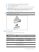
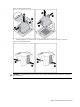
• Do not sharply bend any cable. A sharp bend can break the internal wires.
• Never bend a SATA data cable tighter than a 30 mm (1.18 in) radius.
• Never crease a SATA data cable.
• Do not rely on components like the drive cage, power supply, or system cover to push cables
down into the chassis.
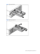
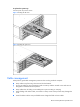
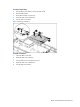
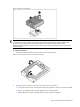
To remove the power supply cables from the system board connectors (J36):
1. Squeeze on the top of the retaining latch attached to the cable end of the connector.
2. Grasp the cable end of the connector and pull it straight up.
CAUTION: Always pull the connector - NEVER pull on the cable. Pulling on the cable could damage
the cable and result in a failed power supply.
Figure 5 Unplugging power cables
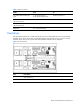
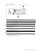
Cable connections
The following table provides information about cable connector.
Table 1
Cable connections
Cable From To
System board power cable (left
and right trays)
J2 on the personality board J36 on system board
RPS cable (left and right trays) J3 on the personality board J42 on system board
Front SATA cable (left and right
trays)
J32, J9 on the system board
P1, P2 on the personality board
SFF HDD (configure 1)
Front SATA cable (left and right
trays)
J32 on the system board
P1 on the personality board
LFF HDD (configure 2)
Rear SATA cable (left and right
trays)
J18, J19 on the system board
P3, P4 on the personality board
SFF HDD (configure 1)