HP ProLiant SL390s G7 2U Half-width Server Maintenance and Service Guide Part number 614097-004 Fourth edition March 2013
Legal notices © Copyright 2010, 2013 Hewlett-Packard Development Company, L.P. The information contained herein is subject to change without notice. The only warranties for HP products and services are set forth in the express warranty statements accompanying such products and services. Nothing herein should be construed as constituting an additional warranty. HP shall not be liable for technical or editorial errors or omissions contained herein. Microsoft® and Windows® are U.S.
Contents Customer self repair ............................................................................................................................... 5 Parts only warranty service ........................................................................................................................ 5 Illustrated parts catalog ......................................................................................................................... 16 Mechanical components ...........................
HP ROM-Based Setup Utility .................................................................................................................... 81 HP Insight Diagnostics ............................................................................................................................ 81 Integrated Management Log .................................................................................................................... 82 Array Diagnostic Utility ...........................................
Customer self repair HP products are designed with many Customer Self Repair (CSR) parts to minimize repair time and allow for greater flexibility in performing defective parts replacement. If during the diagnosis period HP (or HP service providers or service partners) identifies that the repair can be accomplished by the use of a CSR part, HP will ship that part directly to you for replacement. There are two categories of CSR parts: • Mandatory—Parts for which customer self repair is mandatory.
Réparation par le client (CSR) Les produits HP comportent de nombreuses pièces CSR (Customer Self Repair = réparation par le client) afin de minimiser les délais de réparation et faciliter le remplacement des pièces défectueuses. Si pendant la période de diagnostic, HP (ou ses partenaires ou mainteneurs agréés) détermine que la réparation peut être effectuée à l'aide d'une pièce CSR, HP vous l'envoie directement.
Riparazione da parte del cliente Per abbreviare i tempi di riparazione e garantire una maggiore flessibilità nella sostituzione di parti difettose, i prodotti HP sono realizzati con numerosi componenti che possono essere riparati direttamente dal cliente (CSR, Customer Self Repair). Se in fase di diagnostica HP (o un centro di servizi o di assistenza HP) identifica il guasto come riparabile mediante un ricambio CSR, HP lo spedirà direttamente al cliente per la sostituzione.
Customer self repair HP Produkte enthalten viele CSR-Teile (Customer Self Repair), um Reparaturzeiten zu minimieren und höhere Flexibilität beim Austausch defekter Bauteile zu ermöglichen. Wenn HP (oder ein HP Servicepartner) bei der Diagnose feststellt, dass das Produkt mithilfe eines CSR-Teils repariert werden kann, sendet Ihnen HP dieses Bauteil zum Austausch direkt zu.
Reparaciones del propio cliente Los productos de HP incluyen muchos componentes que el propio usuario puede reemplazar (Customer Self Repair, CSR) para minimizar el tiempo de reparación y ofrecer una mayor flexibilidad a la hora de realizar sustituciones de componentes defectuosos.
Customer self repair Veel onderdelen in HP producten zijn door de klant zelf te repareren, waardoor de reparatieduur tot een minimum beperkt kan blijven en de flexibiliteit in het vervangen van defecte onderdelen groter is. Deze onderdelen worden CSR-onderdelen (Customer Self Repair) genoemd.
Reparo feito pelo cliente Os produtos da HP são projetados com muitas peças para reparo feito pelo cliente (CSR) de modo a minimizar o tempo de reparo e permitir maior flexibilidade na substituição de peças com defeito. Se, durante o período de diagnóstico, a HP (ou fornecedores/parceiros de serviço da HP) concluir que o reparo pode ser efetuado pelo uso de uma peça CSR, a peça de reposição será enviada diretamente ao cliente.
Customer self repair 12
Customer self repair 13
Customer self repair 14
Customer self repair 15
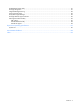
Illustrated parts catalog Mechanical components Item Description Spare part number Customer self repair 1 Front GPU bracket — — 2 2U left tray — — 3 Left front I/O bezel — — 4 Front PCIe bracket — — 5 Top power bracket — — 6 Single GPU bottom bracket — — 7 HDD cage — — 8 Right front I/O bezel — — 9 2U right tray — — 10 Power supply top cover — — Illustrated parts catalog 16
Mandatory—Parts for which customer self repair is mandatory. If you request HP to replace these parts, you will be charged for the travel and labor costs of this service. 1 Optional—Parts for which customer self repair is optional. These parts are also designed for customer self repair. If, however, you require that HP replace them for you, there may or may not be additional charges, depending on the type of warranty service designated for your product.
Mandatory: Obligatorio—componentes para los que la reparación por parte del usuario es obligatoria. Si solicita a HP que realice la sustitución de estos componentes, tendrá que hacerse cargo de los gastos de desplazamiento y de mano de obra de dicho servicio. 1 Optional: Opcional— componentes para los que la reparación por parte del usuario es opcional. Estos componentes también están diseñados para que puedan ser reparados por el usuario.
Illustrated parts catalog 19
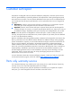
System components Item Description Spare part number Customer self repair 1 System board 620753-001 Optional2 2 PCIe x24 riser card 620824-001 Optional2 PCIe x16 riser card 536654-001 Optional2 3 Rear GPU riser card 620766-001 Optional2 4 Front GPU riser card 620762-001 Optional2 5 Front PCIe card 614097-001 Optional2 6 Hot-plug drive options — — SSD 64GB SFF 461333-001 Optional2 SSD 60GB SFF 586656-001 Optional2 SSD 120GB SFF 586657-001 Optional2 Hard drive, SAS 300G
Item Description Spare part number Customer self repair Hard drive, SAS 2TB 15K LFF 575057-001 Optional2 Hard drive, SAS 300MB 10K SFF 575055-001 Optional2 Non-hot-plug quick release hard drives — — Hard drive, SATA 160GB 7.2K SFF 575053-001 Optional2 Hard drive, SATA 500GB 7.
Item Description Spare part number Customer self repair Processor Intel ZX5687 3.60GHz/1333/12M/4c/6.
Item Description Spare part number Customer self repair 18 1200-W power supply 498152-001 1200-W power supply High-Efficiency 579229-001 750-W power supply Mandatory1 511778-001 750-W power supply High-Efficiency 599383-001 Power/data backplane board 620752-001 Mandatory1 SATA power/data MSAR1 cable 600672-001 Optional2 SATA power/data MSAR2 cable 600673-001 Optional2 RPS cable, right 621292-001 Optional2 RPS cable, left 621293-001 Optional2 Power converter internal cable, right
Mandatory—Parts for which customer self repair is mandatory. If you request HP to replace these parts, you will be charged for the travel and labor costs of this service. 1 Optional—Parts for which customer self repair is optional. These parts are also designed for customer self repair. If, however, you require that HP replace them for you, there may or may not be additional charges, depending on the type of warranty service designated for your product.
Mandatory: Obligatorio—componentes para los que la reparación por parte del usuario es obligatoria. Si solicita a HP que realice la sustitución de estos componentes, tendrá que hacerse cargo de los gastos de desplazamiento y de mano de obra de dicho servicio. 1 Optional: Opcional— componentes para los que la reparación por parte del usuario es opcional. Estos componentes también están diseñados para que puedan ser reparados por el usuario.
Illustrated parts catalog 26
HP contact information For United States and worldwide contact information, see the Contact HP website at http://hp.com/go/assistance. In the United States: • To contact HP by phone, call 1-800-334-5144. For continuous quality improvement, calls may be recorded or monitored. • If you have purchased a Care Pack (service upgrade), see the Support & Drivers website at http://www8.hp.com/us/en/support-drivers.html. If the problem cannot be resolved at the website, call 1-800-633-3600.
Removal and replacement procedures This chapter provides subassembly/module-level removal and replacement procedures for the HP ProLiant SL390s G7 2U Half-width Server. Review the specifications of a new component before installing it to make sure it is compatible with the server. When you integrate new components into the system, record its model and serial number, and any other pertinent information for future reference.
• • • Avoid touching pins, leads, or circuitry. Always place drives with the Printed Circuit Board (PCB) assembly-side down. Use conductive field service tools. Pre-installation procedure Perform the steps below before you open the server or before you remove or replace any component. WARNING: Failure to properly turn off the server before you open the server or before your start installing/removing components may cause serious damage as well as bodily harm. 1.
WARNING: To reduce the risk of personal injury from hot surfaces, allow the drives and the internal system components to cool before touching them. CAUTION: Do not operate the server for long periods with the access panel open or removed. Operating the server in this manner results in improper airflow and improper cooling that can lead to thermal damage. CAUTION: The following rack-mount instructions shall be paid attention to.
This symbol indicates that the component exceeds the recommended weight for one individual to handle safely. To reduce the risk of personal injury or damage to the equipment, observe local occupational health and safety requirements and guidelines for manual material handling. These symbols, on power supplies or systems, indicate that the equipment is supplied by multiple sources of power.
Figure 1 Removing the left server Figure 2 Removing the right server Removal and replacement procedures 32
To replace the system tray: 1. Insert the system tray into the chassis. 2. Rotate the tray handle to lock the power connector. Figure 3 Installing the left server Figure 4 Installing the right server Cable management Always follow good cable management practices when working inside the computer. • • Keep cables away from major heat sources like the heatsink. • • Keep cables clear of sliding or moveable parts to prevent cutting or crimping. • Some flat ribbon cables come pre-folded.
• • • • Do not sharply bend any cable. A sharp bend can break the internal wires. Never bend a SATA data cable tighter than a 30 mm (1.18 in) radius. Never crease a SATA data cable. Do not rely on components like the drive cage, power supply, or system cover to push cables down into the chassis. To remove power supply cables from the system board connectors (J36): 1. Squeeze on the top of the retaining latch attached to the cable end of the connector. 2.
Table 1 Cable connections Cable From To Inner SATA cable J25, J22 on the system board P1, P2 on the personality board SATA HDD Mini-SAS cable (right angle to straight ) J9, J10, J11, J13 on the PCIe x24 riser cable J1, J2, J3, J4 on the rear riser Rear riser and bottom GPU power cables (left and right trays) J2 on the L2 power board 4-pin rear riser (J5) and 8-pin bottom GPU Top two GPU power cables (left and right trays) J3 on the L2 power board 2 x 8-pin top front/rear GPUs Health LED J21
Figure 7 SFF non-hot-plug drive locations Item Description 1 SAS/SATA drive 1 2 SAS/SATA drive 2 3 SAS/SATA drive 3 4 SAS/SATA drive 4 5 SAS/SATA drive 5 6 SAS/SATA drive 6 To remove a hard drive: 1. Press the latch to release the hard drive handle. 2. Rotate the handle. 3. Use the handle to pull the hard drive assembly out of the drive bay.
Figure 8 Removing a hot-plug drive 4. Press the latch to release the hard drive assembly. 5. Remove the hard drive assembly out of the tray.
To install a hard drive: 1. Push the hard drive assembly into the drive bay until it stops. 2. Press the hard drive carrier handle inward until it clicks. Figure 10 Installing a hot-plug hard drive 3. Install the hard drive assembly on the tray and make sure the notch on the carrier locked on the tray. Figure 11 Installing a non-hot-plug drive IMPORTANT: Do not discard the hard drive blank.
SAS/SATA HDD backplane To remove the HDD backplane: 1. Disconnect all HDD backplane cables. 2. Remove the two screws that secure the backplane to the hard drive cage. 3. Pull the backplane out to release it from the hard drive cage. Figure 12 Removing the HDD backplane To install the HDD backplane: 1. Make the screw holes on the backplane align with the holes on the hard drive cage. 2. Secure the backplane with two screws. 3. Connect all HDD backplane cables.
System board configuration Processor The HP ProLiant SL390s G7 2U Half-width Server, with four nodes, supports eight-processor operation. With two processors installed, each node supports boot functions through the processor installed in processor socket 1. However, if processor 1 fails, the system automatically boots from processor 2 and provides a processor failure message.
1. Loosen the first screw about three quarters out, then loosen the second screw completely. 2. Completely loosen the second screw. 3. Lift the heatsink away from the system board. Figure 15 Removing the heatsink IMPORTANT: If the heatsink has been removed for any reason on a previously installed processor, it is critical that you apply more thermal interface material to the integrated heat spreader on the processor to ensure proper thermal bonding between the processor and the heatsink.
Figure 15 Removing a processor 3. Carefully rotate the tool, and then push in and release the tabs to secure the processor in the tool. Figure 16 Securing a processor CAUTION: To avoid damage to the processor, do not touch the bottom of the processor, especially the contact area.
To install a new processor: 1. Carefully insert the processor into the processor installation tool. Handle the processor by the edges only, and do not touch the bottom of the processor, especially the contact area. Figure 17 Inserting a processor 2. Be sure the tool is oriented correctly. Align the processor installation tool with the socket, and then install the processor. THE PINS ON THE SYSTEM BOARD ARE VERY FRAGILE AND EASILY DAMAGED.
Figure 18 Installing a processor CAUTION: THE PINS ON THE SYSTEM BOARD ARE VERY FRAGILE AND EASILY DAMAGED. To avoid damage to the system board: • Never install or remove a processor without using the processor installation tool. • Do not touch the processor socket contacts. • Do not tilt or slide the processor when lowering the processor into the socket. 3. Press and hold the tabs on the processor installation tool to separate it from the processor, and then remove the tool.
Figure 19 Removing the processor installation tool 4. Close the processor socket retaining bracket and the processor locking lever. CAUTION: Be sure to close the processor socket retaining bracket before closing the processor locking lever. The lever should close without resistance. Forcing the lever closed can damage the processor and socket, requiring system board replacement.
To apply the thermal grease compound: 1. Use the alcohol pad provided in the spare part kits or a clean cloth dipped in rubbing alcohol to clean the contact surface on the heatsink and on the new processor. Wipe the contact surfaces several times to make sure that no particles or dust contaminants are evident. 2. Apply all the grease to the top of the processor in the following pattern to ensure even distribution.
Figure 22 Installing the heatsink Memory The HP ProLiant SL390s G7 2U Half-width Server has 12 DIMM slots that support up to 96 GB maximum system memory. You must adhere to the following guidelines when adding or replacing memory modules: • • • • • • • • Support 12 DDR3 240-pin RDIMM (SR, DR, QR) or UDIMM (SR, DR) slots (6 DIMMs per CPU). Channel 0 is located furthest to processor, followed by channel 1 then channel 2. DIMM 0 is the furthest from the processor of the two DIMMs in a given channel.
Figure 23 DIMM slots Figure 24 DIMM order To remove a memory module: 1. Completely open the holding clips securing the module. 2. Gently pull the memory module upward to remove it from the slot.
Figure 25 Removing a memory module CAUTION: Place the memory module on a static-dissipating work surface or inside of an anti-static bag. To install a memory module: NOTE: The HP ProLiant SL390s G7 2U Half-width Server supports up to 12 memory modules. Install them in the DIMM slots starting from the DIMM 1 slot. 1. Align the notch on the bottom edge of the module with the keyed surface of the DIMM slot and then press the module fully into the slot. 2.
PCI expansion cards System board PCI expansion slots There is one PCIe x24 expansion slot for riser board installation on the system board. Figure 27 System board PCI expansion slot To install the PCIe x24 riser card: 1. Install the riser card to the front PCIe bracket. Figure 28 Installing the riser card 2. Install the optional PCIe card.
Figure 29 Installing an optional front PCIe card 3. Install the front x24 riser card assembly to the tray.
Battery-backed write cache procedures 1. Align the BBWC bracket to the tray and fasten the screws. Figure 31 Installing the BBWC bracket 2. Install the BBWC into the tray and slide it in the direction of the arrow.
3. Connect the BBWC cable to an HP Smart Array controller. Figure 33 BBWC cable routing System battery The server uses nonvolatile memory that requires one battery per system board to retain system information when power is removed. This 3-volt lithium coin cell battery is located on the system board. Figure 34 System battery location WARNING: Note the following reminders when replacing the system battery: • Replace the battery with the same type as the battery recommended by HP.
CAUTION: Loss of BIOS settings occurs when the battery is removed. You must reconfigure BIOS settings whenever you replace the battery. NOTE: If the server no longer automatically displays the correct date and time, you may need to replace the system battery. Under normal usage, battery life is five to ten years. To replace the system battery: 1. Release the battery from its holder; squeeze the metal clamp that extends above top of the battery. When the battery pops up, lift it out. 2.
Figure 36 Removing the system board IMPORTANT: Do not discard the screws. If the system board is removed in the future, you must keep them for future use. To replace the system board: 1. Put the system board in the tray. The screw holes on the tray should align with the holes on the system board. 2. Fasten the screws to secure the system board to the tray.
Personality board To remove the personality board: 1. Remove the five screws that secure the personality board to the tray. 2. Release the personality board from the tray. Figure 38 Removing the personality board To install the personality board: 1. Put the personality board in the tray. The screw holes on the tray should align with the holes on the personality board. 2. Fasten the screws to secure the personality board to the tray.
Power supply unit Located on the rear panel of the server power supply is a standard ranging 750 W or 1200 W power supply unit (PSU) with PFC (power factor correction) function. Figure 40 Power supply unit WARNING: Take note of the following reminders to reduce the risk of personal injury from electric shock hazards and/or damage to the equipment.
To remove the power supply: 1. Press the port colored button on the power supply latch. 2. Slide the power supply out of the power supply bay. Figure 42 Removing the power supply To replace the PSU backplane: 1. Remove the top cover from the power supply cage. 2. Install the PSU backplane. 3. Reinstall the top cover to the power supply cage.
To replace the power supply: 1. Align the power supply edge card connector with the open slot of power supply cage. 2. Slide the power supply into the power supply bay until it snaps into place. Figure 44 Installing the power supply System fan The server has eight system fans located on the rear panel of chassis. The figure below identifies the system fans by their device number.
Item Description 3 Fan 3 4 Fan 4 5 Fan 5 6 Fan 6 7 Fan 7 8 Fan 8 A new system fan can be installed to allow the server to operate properly in case a default system fan becomes defective. To remove the system fan: 1. Squeeze the two release tabs on the system fan together to release it from the chassis. 2. Lift the system fan away from the chassis.
To replace the system fan: Insert the system fan into the chassis.
Item Description 1 GPU 2 on left/right tray ( top-front) 2 GPU 1 on left/right tray (top-tear) 3 GPU 3 on left/right tray (bottom-rear) GPU power capping Table 2 GPU power capping information GPU installation Max inlet temperature L2 power board Node power Chassis DC power 1@250W 35°C 250W 658W 2989W 2@250W 35°C 447W 908W 3989W 3@225W 30°C 641W 1158W 4989W NOTE: • 3 GPU power was calculated at 250W.
2. Remove the HDD module out of the tray. Figure 49 Removing the HDD module 3. Unfasten the screws securing the 2 GPU bracket to the tray. 4. Remove the 2 GPU bracket out of the tray.
Installing the single GPU option 1. Install the GPU extension bracket on the M2050 or M2070 GPU. NOTE: Skip this step if installing an M1060 GPU. Figure 51 Installing the GPU extension bracket 2. Install the GPU on the rear GPU assembly and fasten the screws.
3. Connect the rear GPU cables. Figure 53 Connecting the rear GPU assembly cables t the GPU 4. Install the rear GPU assembly on the bottom of 2U tray and fasten the screws to secure it to the tray.
5. Connect the rear GPU assembly cables to the x24 riser card. Figure 55 Connecting the rear GPU assembly cables to the x24 riser card Installing the 2 GPU riser option 1. Install the front GPU riser card to the 2 GPU bracket. Figure 56 Installing the front GPU riser card 2. Install the IOH mezz assembly: a. Insert the IOH mezz assembly to the front riser card. b. Fasten the screws to secure the IOH mezz assembly to the 2 GPU bracket.
Figure 57 Installing the IOH mezz assembly Installing the 2 GPU bracket assembly 1. Install the GPU extension bracket to the M2050 and M2070 GPUs. NOTE: Skip this step if installing an M1060 GPU. Figure 58 Installing the GPU extension bracket 2. Install the GPUs to the 2 GPU bracket.
Figure 59 Installing the GPUs on the 2 GPU bracket 3. Install the 2 GPU bracket into the tray and fasten the screws to secure it to the tray. Figure 60 Installing the 2 GPU bracket into the tray 4. Reinstall the HDD module and fasten the screws.
Figure 61 Reinstalling the HDD module Removal and replacement procedures 69
Connectors, switches, and LEDs This chapter contains illustrations and tables identifying and describing the connectors, switches, buttons, and LED indicators of the HP ProLiant SL390s G7 2U Half-width Server.
Item Description 13 HDD 3 14 HDD 4 15 iLO 3 connector Rear panel components Figure 63 Rear panel components Item Description 1 Power supply 1 2 Power supply 2 3 Power supply 3 4 Power supply 4 5 UID LED/SW 6 APM connector 7 Fan 1 8 Fan 2 9 Fan 3 10 Fan 4 11 Fan 5 12 Fan 6 13 Fan 7 14 Fan 8 Connectors, switches, and LEDs 71
System board components Figure 64 System board components Item Designator Description 1 J38 Serial connector 2 SW3 Power LED/SW 3 J30 QSFP cage 4 J41 Top: NIC 1 connector Bottom: NIC 2 connector 5 J37 Top: ILO connector Bottom: USB 2.
Item Designator Description 12 @U10, CPU2 VRD and CPU1 DIMM VRD @U22, @U41, @U51, @U12, @U10, @U14, @U11 13 XU2 Processor 2 socket 14 J1 Processor 1 DDR3 DIMM slot J2 Processor 1 DDR3 DIMM slot J4 Processor 1 DDR3 DIMM slot J5 Processor 1 DDR3 DIMM slot J7 Processor 1 DDR3 DIMM slot J8 Processor 1 DDR3 DIMM slot 15 XU1 Processor 1 socket 16 J42 RPS connector 17 J36 Power connector 18 @U24, Processor 1 VRD @U5 @U4 @U30 @U27 19 J10 Processor 2 DDR3 DIMM slot J11 Processor
Serial port connection is compatible with the DIGI CM RJ-45 and Sun/Cisco RJ-45. Straight Cat 5e cable can be used for this interface. For connecting to Cyclades connection, use ADB2239. For connecting to DB9M connection, use rolled cat5e and digi76000702 or manually wire with Digikey P/N 046-0000-ND.
Table 5 System maintenance switch Position Description Definition 8:7 Reserved [8:7] = LED Control Main Power OFF: OFF = Port85 OFF:ON = iLO ON:OFF = Port84 ON:ON = System CPLD Version Aux Power OFF: OFF = iLO OFF:ON = iLO ON:OFF = Reserved ON:ON = Reserved ON:ON = RMII CPLD Version 10:9 Chassis ID [10:9] = Chassis ID 00 = Standard system configuration (Spartan) 01 = Areus Chassis 10 = T2/Optimus Chassis 11= Reserved Table 6 Personality board switches Tray type Minimum voltage (Volt) Norminal vol
Table 6 Personality board switches Tray type Norminal voltage (Volt) Maximum voltage (Volt) Resistor pull down value (KOhms, 1%) Tray ID Resistor pull up value (KOhms, 1%) 0.86 0.91 1.969 5.6 0x09 0.66 0.71 0.76 1.536 5.6 0x08 0.53 0.57 0.61 1.174 5.6 0x07 0.41 0.44 0.47 0.872 5.6 0x06 0.30 0.32 0.35 0.612 5.6 0x05 0.23 0.24 0.26 0.449 5.6 0x14 0.19 0.20 0.22 0.368 5.6 0x13 0.15 0.16 0.17 0.286 5.6 0x12 0.13 0.14 0.14 0.239 5.6 0x11 0.0 0.0 0.
LED indicators This section contains illustration and descriptions of external status LED indicators located on the: • • Front panel Rear panel These LED indicators aid in problem diagnosis by indicating the status of system components and operations of the server. Front panel LED indicators The front panel LED indicators allow constant monitoring of basic system functions while the server is operating.
Front UID LED indicator Figure 66 Front UID LED indicator locations Table 8 UID LED indicator status Components Status Descriptions UID LED indicator Blue Identification Flashing blue System is being remotely managed Off Off Connectors, switches, and LEDs 78
Power LED indicator The power status of the server is indicated by the bicolor LED on the front panel. Figure 67 Power LED indicator locations Table 9 Power/system health LED indicator status Component Status Description Power/system health LED indicator Steady green The server is operating normally. Steady amber The server is system off or in hibernation with AC power. Steady red Critical event happens to the server. See SEL for details. Off The server is system off without AC power.
Rear panel UID LED indicators The UID LED indicator allows monitoring of network activity.
Diagnostic tools Troubleshooting resources The HP ProLiant Servers Troubleshooting Guide provides procedures for resolving common problems and comprehensive courses of action for fault isolation and identification, error message interpretation, issue resolution, and software maintenance on ProLiant servers and server blades. This guide includes problem-specific flowcharts to help you navigate complex troubleshooting processes. To view the guide, select a language: English (http://www.hp.
NOTE: The current version of SmartStart provides the memory spare part numbers for the server. To download the latest version, see the HP website (http://www.hp.com/support). Integrated Management Log The IML records hundreds of events and stores them in an easy-to-view form. The IML timestamps each event with 1-minute granularity.
HP Insight Remote Support software HP Insight Remote Support software delivers secure remote support for your HP Servers and Storage, 24 X 7, so you can spend less time solving problems and more time focused on your business. You can have your systems remotely monitored for hardware failure using secure technology that has been proven at thousands of companies around the world. In many cases, you can avoid problems before they occur.
Internal USB functionality An internal USB connector is available for use with security key devices and USB drive keys. This solution provides for use of a permanent USB key installed in the internal connector, avoiding issues of clearance on the front of the rack and physical access to secure data. For additional security, external USB functionality can be disabled through RBSU. Disabling external USB support in RBSU disables the USB connectors on the local I/O cable.
Physical and operating specifications This chapter provides physical and operating specifications for the HP ProLiant SL390s G7 2U Half-width Server.
Table 12 Physical dimensions Item Description System board platform ATX (Advanced Technology Extended) System board dimension 17.935’’x6.5’’ Dimensions (H x W x D) 6.96 x 17.64 x 35.32 inch (with bezel) Server weight (approximate) Full loading (all memory, hard drives, power supplies, and processors installed) 70.2kg Light loading (one piece of memory, one hard drive, and one processor 8 trays installed) 58.
Table 13 Environmental specifications Item Description Emissions classification (EMC) FCC rating Class A Normative standards CISPR 22; EN55022; EN55024; FCC CFR 47, Pt 15; ICES-003; CNS13438; GB9254; K22;K24; EN 61000-3-2; EN 61000-3-3; EN 60950-1; IEC 60950-1 Table 14 Hot-plug power supply specifications Item Description Dimensions (H x W x D) 38.48 mm x 86.36 mm x 190.52 mm Weight (approximate) 1.
Documentation feedback HP is committed to providing documentation that meets your needs. To help us improve the documentation, send any errors, suggestions, or comments to Documentation Feedback (mailto:docsfeedback@hp.com). Include the document title and part number, version number, or the URL when submitting your feedback.
Index Hard Drive A Array Diagnostic Utility (ADU), 82 B back plane, 39 backplane installing, 39 removing, 39 battery replacement warnings, 53 C spare part number, 20 hardware configuration 3 GPU, 64, 66 hardware configuration hard drives, 35 memory, 47 processor, 40 references, 28 system battery, 53 system fan, 59 cable management, 33 Hardware configuration tools, 28 CSR (customer self repair), 5 hardware specifications customer self repair (CSR), 5 I/O ports, 85 D LAN controller, 85 diagnostic
HP Insight Diagnostics, 81 power supply unit.
system board configuration System Unit PCI expansion cards, 50 specifications, 85 System Board Configuration, 40 Systems Insight Manager, 82 system fan T removing, 60 replacing, 61 System fan spare part number, 22 system LEDs.