HP ProLiant SL6000/SL6500 Scalable System Cabling Guide Abstract This document is for the person who installs, administers, and troubleshoots servers and storage systems. HP assumes you are qualified in the servicing of computer equipment and trained in recognizing hazards in products with hazardous energy levels.
© Copyright 2009, 2014 Hewlett-Packard Development Company, L.P. The information contained herein is subject to change without notice. The only warranties for HP products and services are set forth in the express warranty statements accompanying such products and services. Nothing herein should be construed as constituting an additional warranty. HP shall not be liable for technical or editorial errors or omissions contained herein. Microsoft® is a U.S. registered trademark of Microsoft Corporation.
Contents Hardware installation .................................................................................................................... 4 Scalable system hardware ............................................................................................................................ 4 Rack types and configurations ....................................................................................................................... 4 Rack compatibility .......................................
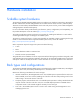
Hardware installation Scalable system hardware The HP ProLiant SL6000/SL6500 Scalable System is a modular server hardware system that is optimized for HP Rack 10000 Series and HP Intelligent Rack Series models that are at least 47.24 in (1200 mm) deep. These are universal industry standard RETMA 19-inch racks with proven air flow, proven cable management and high dynamic and static load capacity.
Rack compatibility In general, the SL6500 Scalable System requires a deeper rack than the SL6000 Scalable System. In some cases, a rack extender can provide the necessary depth. HP Intelligent Rack Third-party rack Series Server chassis HP 10000 Rack Series SL6000 47.24 in (1200 mm) 47.24 in (1200 mm) Minimum 1000 mm deep, RETMA 19-inch rails and sufficient load capacity 47.24 in (1200 47.
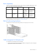
• Using the cable management bracket that ships with the 2U and 4U rack-mounting hardware kit. The following figure shows the cable management solution installed on a third-party rack. Optional installation services Delivered by experienced, certified engineers, HP Care Pack services help you keep your servers up and running with support packages tailored specifically for HP ProLiant systems. HP Care Packs let you integrate both hardware and software support into a single package.
For more information on HP Care Pack Services, see the HP website (http://www.hp.com/services/carepack). Optimum environment When installing the server in a rack, select a location that meets the environmental standards described in this section. Space and airflow requirements To allow for servicing and adequate airflow, observe the following space and airflow requirements when deciding where to install a rack: • Leave a minimum clearance of 63.5 cm (25.0 in) in front of the rack.
The maximum recommended ambient operating temperature (TMRA) for most server products is 35°C (95°F). The temperature in the room where the rack is located must not exceed 35°C (95°F). CAUTION: To reduce the risk of damage to the equipment when installing third-party options: • Do not permit optional equipment to impede airflow around the server or to increase the internal rack temperature beyond the maximum allowable limits. • Do not exceed the manufacturer’s TMRA.
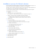
Installation guidelines Always install the scalable system in consecutive U spaces in the rack to optimize cooling, cabling, and management functions. Before installing scalable system components and options, observe all safety information and guidelines in product-specific documentation. Also observe the following guidelines. WARNING: To reduce the risk of personal injury or damage to the equipment, be sure that: • • • • • The leveling feet are extended to the floor.
Installation overview for full-rack solutions For ease of cabling, HP recommends a specific order for hardware installation and cable connections. You can use portions of the procedure, depending on the hardware in your configuration. The number of power components is based on the number of servers and the power supply configuration. For more information, see "Power requirements and considerations (on page 11).
Power cabling Power requirements and considerations When calculating power for the scalable system, be sure to include power for network switches, UPS devices, and other options. To supply adequate power to the scalable system, observe the power input requirements for each type of server power supply, and then provide the sufficient number of PDUs and distribution cables or devices.
An HP fixed-cord extension bar has four cords with power connectors. Depending on the server power supply configuration, each extension bar can support the following: • Up to two servers (with two power supplies) • Up to four servers (with one power supply) For a fully-configured 42U rack with two switches and 20 servers with two power supplies, 11 extension bars are required. For a list of supported extension bars, see the product QuickSpecs on the HP website (http://www.hp.com/go/qs).
mPDU and fixed-cord extension bar configuration The following figure shows a 42U rack with two mPDUs installed in a zero-U configuration. Five fixed-cord extension bars are connected to each mPDU.
Power cabling with extension bars Fixed-cord extension bars enable you to reduce traditional power cabling with the following methods: • Eliminating standard-length power cords for each server power supply • Aggregating server cabling into fewer PDU connections The following figure shows the back of a fully-configured 42U rack with different types of scalable system servers.
Power cabling with Y-cables For servers with 1200-W power supplies, Y-cables are specialized power cords that connect two power supplies to a single C19 PDU outlet. Y-cables eliminate the need for extension bars (power strips) and can provide lower cost, easier installation, and less clutter in the rack. The following figure shows the side and back of a fully-configured 42U rack with different types of scalable system servers.
Bottom-mounted mPDU and fixed-cord extension bar configuration The following figure shows a 42U rack with two 3-phase mPDUs installed in the bottom of the rack. Five fixed-cord extension bars are connected to each mPDU. The cables to the extension bars are routed from the back of the mPDUs.
Item Description 3 Fixed-cord mPDU Power cabling with Y-cables and bottom-mounted PDU For servers with 1200-W power supplies, Y-cables are specialized power cords that connect two power supplies to a single C19 PDU outlet. Y-cables eliminate the need for extension bars (power strips) and can provide lower cost, easier installation, and less clutter in the rack. The following figure shows the side and back of a 42U rack with different types of scalable system servers.
For illustration purposes only, the right rear rack column is removed to show cable routing.
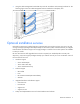
Network cabling Network adapter and switch support Each server model in the HP ProLiant SL6000/SL6500 Scalable System supports a network adapter with at least one connector. For server-specific connector locations, see the server installation sheet that ships with the server. For a fully configured 42U rack, HP recommends installing two 1U switches at the 21U and 22U positions in the rack.
The servers in the bottom half of the rack have a redundant adapter cabling configuration. Network cabling with InfiniBand switches By mounting InfiniBand switches with connectors at the rear of the rack, you can eliminate in-rack routing and bending of the InfiniBand cables from the external network. This configuration also keeps the InfiniBand connections isolated at the back of the rack, reducing physical interference with SFP transceivers.
The following figure shows a fully configured rack with two 1U Infiniband switches and different types of scalable system servers. Adapter cabling consists of QDR cables with QSFP connectors. Connections from the servers to the switches show cabling that routes from the front to the rear of the rack.
Electrostatic discharge Preventing electrostatic discharge To prevent damaging the system, be aware of the precautions you need to follow when setting up the system or handling parts. A discharge of static electricity from a finger or other conductor may damage system boards or other static-sensitive devices. This type of damage may reduce the life expectancy of the device. To prevent electrostatic damage: • Avoid hand contact by transporting and storing products in static-safe containers.
Support and other resources Before you contact HP Be sure to have the following information available before you call HP: • Active Health System log (HP ProLiant Gen8 or later products) Download and have available an Active Health System log for 3 days before the failure was detected. For more information, see the HP iLO 4 User Guide or HP Intelligent Provisioning User Guide on the HP website (http://www.hp.com/go/ilo/docs).
Acronyms and abbreviations CSA Canadian Standards Association ESD electrostatic discharge IEC International Electrotechnical Commission iLO Integrated Lights-Out mPDU modular power distribution unit PDU power distribution unit QDR quad data rate QSFP quad small form-factor pluggable RDP Rapid Deployment Pack RETMA Radio Electronics Television Manufacturers Association (rack spacing) SFP small form-factor pluggable SIM Systems Insight Manager Acronyms and abbreviations 24
TMRA recommended ambient operating temperature UPS uninterruptible power system Acronyms and abbreviations 25
Documentation feedback HP is committed to providing documentation that meets your needs. To help us improve the documentation, send any errors, suggestions, or comments to Documentation Feedback (mailto:docsfeedback@hp.com). Include the document title and part number, version number, or the URL when submitting your feedback.
Index A N airflow requirements authorized reseller 7 23 network cable 19, 20 O C optimum environment cable management system 5 cables, networking 19, 20 cables, PDU 13, 16 Care Pack 6 contacting HP 23 customer self repair (CSR) 23 P PDU installation 10, 13, 16 phone numbers 23 power cables 11, 12, 13, 14, 15, 16, 17 power distribution unit (PDU) 8, 13, 16 power requirements 8 E electrical grounding requirements electrostatic discharge 22 environmental requirements 7 Ethernet switches 19 extension
V ventilation 7 W website, HP 23 Index 28