
HP ProLiant SL6000/SL6500 Scalable System Cabling Guide


Network cabling 19
Network cabling
Network adapter and switch support
Each server model in the HP ProLiant SL6000/SL6500 Scalable System supports a network adapter with at
least one connector. For server-specific connector locations, see the server installation sheet that ships with
the server.
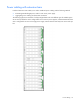
For a fully configured 42U rack, HP recommends installing two 1U switches at the 21U and 22U positions in
the rack. Locating the switches in other positions is supported, but routing cables for those configurations can
be more challenging.
For a list of supported switches, see the product QuickSpecs on the HP website
(http://www.hp.com/go/qs).
To obtain supported switches, contact an HP authorized reseller or see the HP website
(http://www.procurve.com).
Network cabling configurations
Many network cabling configurations are possible, including the following examples:
• Network cabling with Ethernet switches (on page 19)
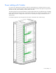
• Network cabling with InfiniBand switches (on page 20)
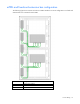
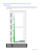
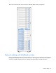
Network cabling with Ethernet switches
By mounting Ethernet switches in the middle of the rack, you can use shorter network cables and further
reduce cable bulk by dividing cable routing between the front left and right columns and between the top and
bottom of the rack.
The following figure shows the front of a fully configured rack with two 1U Ethernet switches and different
types of scalable system servers. Adapter cabling consists of standard network cables with RJ-45 connectors.