HP ProLiant SL4500 Series Setup and Installation Guide Abstract This document contains setup, installation, and configuration information for the HP ProLiant SL4500 Series. This document is for the person who installs, administers, and troubleshoots servers and storage systems. HP assumes you are qualified in the servicing of computer equipment and trained in recognizing hazards in products with hazardous energy levels.
© Copyright 2012, 2014 Hewlett-Packard Development Company, L.P. The information contained herein is subject to change without notice. The only warranties for HP products and services are set forth in the express warranty statements accompanying such products and services. Nothing herein should be construed as constituting an additional warranty. HP shall not be liable for technical or editorial errors or omissions contained herein.
Contents Planning the installation ................................................................................................................. 5 Verifying the pallet contents ........................................................................................................................ 5 Warnings and cautions .............................................................................................................................. 5 Space and airflow requirements ..........................
Electrostatic discharge ................................................................................................................. 49 Preventing electrostatic discharge .............................................................................................................. 49 Grounding methods to prevent electrostatic discharge .................................................................................. 49 Support and other resources ......................................................
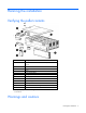
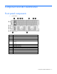
Planning the installation Verifying the pallet contents Item Description 1 The HP ProLiant SL4500 Series chassis (3 node model shown) 2 Nodes* 3 Drive blank* 4 Drive* 5 Power supply blank* 6 Management module 7 Power supply* 8 I/O modules* 9 System fans (5) 10 Access panel 11 Rack rails and cable management arm** 12 Documentation CD** * The quantity depends on the configuration ordered.
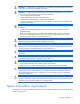
WARNING: To reduce the risk of personal injury or damage to equipment, heed all warnings and cautions throughout the installation instructions. WARNING: To reduce the risk of personal injury or damage to the equipment, be sure that: • • • • • The rack is bolted to the floor using the concrete anchor kit. The leveling feet extend to the floor. The full weight of the rack rests on the leveling feet. The racks are coupled together in multiple rack installations. Only one component is extended at a time.
• Leave a minimum clearance of 61.0 cm (24 in) in front of the rack. • Leave a minimum clearance of 76.2 cm (30 in) in back of the rack. • Leave a minimum clearance of 121.9 cm (48 in) from the back of the rack to the rear of another rack or row of racks. HP rack products draw cool air in through the front and expel warm air through the rear of the enclosure.
CAUTION: Protect the node from power fluctuations and temporary interruptions with a regulating UPS. This device protects the hardware from damage caused by power surges and voltage spikes and keeps the node in operation during a power failure. Grounding requirements This equipment must be grounded properly for proper operation and safety.
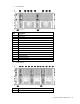
Component and LED identification Front panel components • 1 node chassis Item Description 1 Node drives 2 LFF drive health LED 3 LFF drive UID 4 Drives controlled by the array controller a. Port 1i b.
• 2 node chassis Item Description 1 Node 1 2 Node drives 3 LFF drive health LED 4 LFF drive UID 5 Drives controlled by node 1 P420i array controller 6 Node 2 7 Drives controlled by node 2 P420i array controller 8 Drive display boards 9 Node VGA connector 10 Node USB connectors 11 Node Power On/Standby button and system power LED 12 Node health LED 13 Node release button 14 Node UID LED button • 3 node chassis Item Description 1 Node 1 Component and LED identification 10
Item Description 2 Node drives 3 LFF drive health LED 4 LFF drive UID 5 Drives controlled by node 1 Smart Array controller 6 Node 2 7 Drives controlled by node 2 Smart Array controller 8 Node 3 9 Drives controlled by node 3 Smart Array controller 10 Drive display boards 11 Node VGA connector 12 Node USB connectors 13 Node Power On/Standby button and system power LED 14 Node health LED 15 Node release button 16 Node UID LED button Hard drive display LEDs LED behavior Definiti
LED behavior Definition Solid amber Both of the following conditions apply: Flashing amber at 1Hz 50% duty cycle Alternating amber and green at 1 Hz 50% duty cycle • • Drive is failed. Drive is not selected. All of the following conditions apply: • • • Drive is in a predictive failure state. Drive is not failed. Drive is not selected. • • Drive is failed. Drive is in a predictive failure state. In either instance, the drive is selected.
Item Description Status 3 System Health LED Green = Normal Flashing amber = System degraded Flashing red = System critical 4 Power On/Standby button and system power LED Green = System on Amber = System is in Standby mode, but power is still applied. Off = Power is not connected, or power supply has failed.
• 2 node chassis Item Description 1 System fans 2 I/O module for node 1 3 Management module 4 Power supplies 5 I/O module for node 2 • 3 node chassis Item Description 1 System fans 2 I/O module for node 1 3 Management module 4 I/O module for node 2 5 Power supplies 6 I/O module for node 3 Component and LED identification 14
I/O module connectors and LEDs • 1 Gb I/O module Item Description 1 Activity LED 2 1Gb connectors 3 I/O module health LED 4 Serial connector 5 Link LED • 10 Gb I/O module Item Description 1 1 Gb connectors 2 I/O module health LED 3 QSFP 10 Gb Ethernet or 40Gb IB connector, depending on configuration 4 SFP+ 10Gb Ethernet connector Component and LED identification 15
Item Description 5 Serial connector 6 Link LED 7 Activity LED 8 Activity LED 9 Link LED Description Status Health LED Off = I/O module is in good health. Amber = I/O module has one of the following health issues: • • • Thermal alarm on a mezzanine card I/O module power has failed on one of the power rails. The I/O module is not fully seated in the connector.
Item Description 5 Reserved Description Status UID LED Blue = Activated Flashing blue = System is being remotely managed.
2 node drive bay numbering 3 node drive bay numbering Component and LED identification 18
Power supply LED Power LED Status Off • • • Green AC is present and main 12 V output is enabled. No AC power to power supply units. Check the AC power cord. AC is present. Standby output is on; output is disabled. Power supply failure (includes overvoltage and overtemperature) Fan LED LED color System fan status Off The fan is working or power is off. Solid amber The fan module has failed.
Installation Installation overview To set up and install the chassis: 1. Set up and install the rack. For more information, see the documentation that ships with the rack. 2. Disassemble the chassis ("Disassembling the chassis" on page 20). 3. Install the chassis into the rack ("Installing the chassis" on page 24). 4. Install the chassis components ("Component installation" on page 29) into the chassis. 5.
b.
c. Management module. Loosen the screw securing the management module to the chassis, and then remove the module. d. I/O module CAUTION: To avoid damage to the node, always support the bottom of the node when removing it from the chassis.
e. Node CAUTION: To avoid damage to the device, do not use the removal handle to carry it. 2. Remove the access panel: a. Release the access panel latch. b. Slide the access panel back about 1.5 cm (0.5 in). c. 3. Lift and remove the access panel. Remove all drives: IMPORTANT: Labels are provided so that you can label the drives before installing them. If drives are removed, they must be returned to their original locations. a. Release the handle.
b. Remove the drive. Installing the chassis WARNING: Always use at least two people to lift the chassis into the rack. If the chassis is being loaded into the rack above chest level, a third person must assist with aligning the chassis with the rails while the other two people support the weight of the chassis. WARNING: The chassis is very heavy.
You can install up to seven chassis in a 36U, 1200mm deep rack. If you are installing more than one chassis, install the first chassis in the bottom of the rack, and then install additional chassis by moving up the rack with each subsequent chassis. Plan the rack installation carefully because it is difficult to change the location of components after they are installed.
2. Install the chassis into the J-slot on the rails, and then pull it forward. 3. Push in the release lever, and then install the chassis into the rack. CAUTION: Press and hold the "Push" tab on each rail until the chassis begins to slide into the rack. Then, release the "Push" tabs and continue to slide chassis into the rack. Failure to release the "Push" tabs may cause damage to the rails.
4. For round-hole racks, remove the guide pins and replace them with the guide pins included for round-hole racks.
5. Attach a cage nut to each side of the rack. 6. Align the blanking panel. 7. Secure the blanking panel to the rack.
Component installation Installing a node into the chassis Install the component as indicated. Installing a drive To install the component: IMPORTANT: Labels are provided so that you can label the drives before installing them. If drives are removed, they must be returned to their original locations. 1. Prepare the drive. IMPORTANT: The 3-node chassis supports up to 15 drives per backplane. Always populate drive bays from the rear to the front starting with the highest device bay ID number.
2. Install the drive. 3. Determine the status of the drive from the drive LED definitions. Installing a power supply WARNING: To reduce the risk of electric shock or damage to the equipment: • Do not disable the power cord grounding plug. The grounding plug is an important safety feature. • Plug the power cord into a grounded (earthed) electrical outlet that is easily accessible at all times. • Unplug the power cord from the power supply to disconnect power to the equipment.
To install the component: Insert the power supply into the device bay, and then press firmly until the power supply is seated. Installing the system fan To install the component: Push in on the tabs, and then insert the system fan into the chassis. IMPORTANT: Use the tabs to insert the system fan into the chassis. Do not push in on the system fan grill to install it. Installing an I/O module Install any I/O module options before installing the I/O module into the chassis.
WARNING: To reduce the risk of electric shock, fire, or damage to the equipment, do not plug telephone or telecommunications connectors into RJ-45 connectors. To install the component: 1. Release the I/O handle, and then push the I/O handle down. 2. Insert the I/O module into the chassis, and be sure it is fully seated. 3. Push the I/O module handle up to lock it into place. Installing a management module To install the component: 1. Be sure the handle is in the down position. 2.
3. Press the handle up to lock it into place. 4. Secure the management module to the chassis. I/O module options Installing an expansion board The following instructions apply to both 1Gb and 10Gb I/O module configurations. 1. Power down the node. 2. Disconnect any cables connected to the I/O module.
3. Remove the I/O module. 4. Remove the access panel. 5. Remove the expansion board blank.
6. Install the expansion board bracket. 7. Install the expansion board, and then secure it with two screws.
8. Attach the low profile bracket to any supported low profile option card. For a list of supported option cards, see the QuickSpecs on the HP website (http://www.hp.com). 9. Install the option card. 10. Install the access panel. 11. Install the I/O module. 12. Connect any cables to the I/O module. Installing the 10Gb I/O option 1. Power down the node. 2. Disconnect any cables connected to the I/O module.
3. Remove the I/O module. 4. Remove the access panel. 5. If installed, remove any low profile option card.
6. If installed, remove the expansion board. 7. If installed, remove the expansion board bracket.
8. Remove the Smart Array controller and battery. 9. Install the following items on the 10Gb assembly: a. Smart Array controller and battery b. Expansion board bracket, if necessary c. Expansion board, if necessary d. Low profile option card, if necessary e. Access panel 10. Install the I/O module into the chassis. 11. Connect any cables to the I/O module.
Cabling and powering up the chassis Cabling the chassis After all system hardware is installed, cable the components. See the HP ProLiant SL Servers Site Planning Guide on the Documentation CD or the HP website (http://www.hp.com) for additional cabling and site planning requirements.
Installing the cable management arm IMPORTANT: If you need to hinge the cable management arm on the rear right-hand side of the rack, see the instructions in "Converting the cable management arm for opposite side mounting (on page 43)." Perform these steps to convert the arm to a right-hand swing and install the arm on the right side of the rack.
Cabling and powering up the chassis 42
Converting the cable management arm for opposite side mounting The cable management arm is designed for ambidextrous implementation. You can convert the arm for right-hand swing. IMPORTANT: When converting the cable arm, always be sure to orient the arm with the cable trough facing upward. NOTE: To access some components on the rear of the product, you may need to remove the cable management arm. To convert the cable management arm for opposite side mounting: 1.
2. Move the cable management arm to the right rack rail and align the tab for opposite side mounting. 3. Align and install the cable management arm on the right rack rail. Powering up the system 1. Connect the power cables to the power supplies. 2. Connect the power cables to the power source (UPS or wall outlet) or to an installed PDU. 3. Press the Power On/Standby button on the node.
enclosure, all the resident servers in the enclosure will have the same uniform power cap applied to them until the cap is either modified or canceled. With Insight Display, the enclosure-level power capping feature can be expanded without the need to use the PPIC.EXE utility. A global power cap can be applied to all enclosures with one Insight Display command, or different caps can be applied to user-defined groups by using flexible zones within the same rack.
2. Log in to the node, and then run the PPIC utility. 3.
Troubleshooting Important safety information Familiarize yourself with the safety information in the following sections before troubleshooting the server. Important safety information Before servicing this product, read the Important Safety Information document provided with the server. Symbols on equipment The following symbols may be placed on equipment to indicate the presence of potentially hazardous conditions.
These symbols, on power supplies or systems, indicate that the equipment is supplied by multiple sources of power. WARNING: To reduce the risk of injury from electric shock, remove all power cords to completely disconnect power from the system.
Electrostatic discharge Preventing electrostatic discharge To prevent damaging the system, be aware of the precautions you need to follow when setting up the system or handling parts. A discharge of static electricity from a finger or other conductor may damage system boards or other static-sensitive devices. This type of damage may reduce the life expectancy of the device. To prevent electrostatic damage: • Avoid hand contact by transporting and storing products in static-safe containers.
Support and other resources Before you contact HP Be sure to have the following information available before you call HP: • Active Health System log (HP ProLiant Gen8 or later products) Download and have available an Active Health System log for 3 days before the failure was detected. For more information, see the HP iLO 4 User Guide or HP Intelligent Provisioning User Guide on the HP website (http://www.hp.com/go/ilo/docs).
providers or service partners) identifies that the repair can be accomplished by the use of a CSR part, HP will ship that part directly to you for replacement. There are two categories of CSR parts: • Mandatory—Parts for which customer self repair is mandatory. If you request HP to replace these parts, you will be charged for the travel and labor costs of this service. • Optional—Parts for which customer self repair is optional. These parts are also designed for customer self repair.
Pour plus d'informations sur le programme CSR de HP, contactez votre Mainteneur Agrée local. Pour plus d'informations sur ce programme en Amérique du Nord, consultez le site Web HP (http://www.hp.com/go/selfrepair). Riparazione da parte del cliente Per abbreviare i tempi di riparazione e garantire una maggiore flessibilità nella sostituzione di parti difettose, i prodotti HP sono realizzati con numerosi componenti che possono essere riparati direttamente dal cliente (CSR, Customer Self Repair).
HINWEIS: Einige Teile sind nicht für Customer Self Repair ausgelegt. Um den Garantieanspruch des Kunden zu erfüllen, muss das Teil von einem HP Servicepartner ersetzt werden. Im illustrierten Teilekatalog sind diese Teile mit „No“ bzw. „Nein“ gekennzeichnet. CSR-Teile werden abhängig von der Verfügbarkeit und vom Lieferziel am folgenden Geschäftstag geliefert. Für bestimmte Standorte ist eine Lieferung am selben Tag oder innerhalb von vier Stunden gegen einen Aufpreis verfügbar.
sustituciones que lleve a cabo el cliente, HP se hará cargo de todos los gastos de envío y devolución de componentes y escogerá la empresa de transporte que se utilice para dicho servicio. Para obtener más información acerca del programa de Reparaciones del propio cliente de HP, póngase en contacto con su proveedor de servicios local. Si está interesado en el programa para Norteamérica, visite la página web de HP siguiente (http://www.hp.com/go/selfrepair).
Opcional – Peças cujo reparo feito pelo cliente é opcional. Essas peças também são projetadas para o reparo feito pelo cliente. No entanto, se desejar que a HP as substitua, pode haver ou não a cobrança de taxa adicional, dependendo do tipo de serviço de garantia destinado ao produto. OBSERVAÇÃO: Algumas peças da HP não são projetadas para o reparo feito pelo cliente. A fim de cumprir a garantia do cliente, a HP exige que um técnico autorizado substitua a peça.
Support and other resources 56
Support and other resources 57
Regulatory information Safety and regulatory compliance For safety, environmental, and regulatory information, see Safety and Compliance Information for Server, Storage, Power, Networking, and Rack Products, available at the HP website (http://www.hp.com/support/Safety-Compliance-EnterpriseProducts). Turkey RoHS material content declaration Ukraine RoHS material content declaration Warranty information HP ProLiant and X86 Servers and Options (http://www.hp.
Environmental considerations Communications interference HP system compliance tests are conducted with HP supported peripheral devices and shielded cables, such as those received with the system. The system meets interference requirements of all countries in which it is sold. These requirements provide reasonable protection against interference with radio and television communications.
• Use heel straps, toe straps, or boot straps at standing workstations. Wear the straps on both feet when standing on conductive floors or dissipating floor mats. • Use conductive field service tools. • Use a portable field service kit with a folding static-dissipating work mat. If you do not have any of the suggested equipment for proper grounding, have an authorized reseller install the part.
Acronyms and abbreviations CSA Canadian Standards Association CSR Customer Self Repair ESD electrostatic discharge IEC International Electrotechnical Commission PDU power distribution unit TMRA recommended ambient operating temperature UID unit identification UPS uninterruptible power system USB universal serial bus Acronyms and abbreviations 61
Documentation feedback HP is committed to providing documentation that meets your needs. To help us improve the documentation, send any errors, suggestions, or comments to Documentation Feedback (mailto:docsfeedback@hp.com). Include the document title and part number, version number, or the URL when submitting your feedback.
Index 1 F 10Gb I/O option, installing 36 fan LED 19 fans, installing 31 Federal Communications Commission (FCC) notice 58 A airflow requirements 5, 6 authorized reseller 50 B battery replacement notice 58 BSMI notice 58 C cable configuration 40 cable management arm 41, 43 cables 40 cables, overview 40 cabling 40 Canadian notice 58 chassis, installing server 29 components, identification 9, 12, 13, 17 connectors, I/O module 15 connectors, management module 16 contents 5 CSR (customer self repair) 50 cu
management module connectors 16 management module LEDs 16 minimum requirements 7, 8 modifications, FCC notice 58 N node release button 9 O overview of installation process 20 P PDU (power distribution unit) 8 phone numbers 50 power distribution unit (PDU) 8 power requirements 7 power supplies 30 power supply LEDs 19 powering up 44 powering up the enclosure 40 preparation procedures 5 problem diagnosis 47 T Taiwan battery recycling notice 58 technical support 50 telephone numbers 50 temperature requireme