
HP ProLiant SL4500 Series Setup and Installation Guide

Cabling and powering up the chassis 40
Cabling and powering up the chassis
Cabling the chassis
After all system hardware is installed, cable the components. See the HP ProLiant SL Servers Site Planning
Guide on the Documentation CD or the HP website (http://www.hp.com) for additional cabling and site
planning requirements.
WARNING: To reduce the risk of electric shock or injury due to high-current electrical energy, be
sure that all power is completely disconnected at the source before beginning any power
connections to the power bus bars or power bus box.
WARNING:
Be sure that all circuit breakers are locked in the off position before connecting any
power components.
CAUTION: To avoid damaging the fiber cables, do not drape cables from one side of the rack
to the other and do not run cables over a hard corner or edge.
To cable the system:
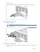
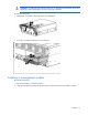
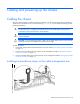
1. Connect the network cables to the Ethernet ports on the I/O module ("I/O module connectors and LEDs"
on page 15).
2. Connect a network cable to the iLO connector on the management module ("Management module
connectors and LEDs" on page 16).
3. Connect a SL-APM cable to the SL-APM connector on the management module ("Management module
connectors and LEDs" on page 16).
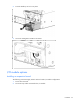
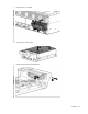
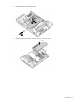
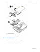
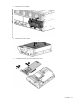
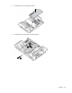
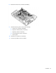
Installing hook-and-loop straps on the cable management arm