HP ProLiant WS460c G6 Workstation Blade with WS460c Graphics Expansion Blade User Guide Abstract This guide provides operation information for the HP ProLiant WS460c G6 Workstation Blade with WS460c Graphics Expansion Blade. This guide is for technicians that install, administer, and troubleshoot servers and storage systems.
© Copyright 2009, 2012 Hewlett-Packard Development Company, L.P. The information contained herein is subject to change without notice. The only warranties for HP products and services are set forth in the express warranty statements accompanying such products and services. Nothing herein should be construed as constituting an additional warranty. HP shall not be liable for technical or editorial errors or omissions contained herein. Microsoft®, Windows®, Windows NT®, Windows® XP, and Windows Server® are U.
Contents Component identification ............................................................................................................... 6 Front panel components ................................................................................................................................ 6 Front panel components for workstation blade with graphics expander blade .................................................... 7 Front panel LEDs ................................................................
Accessing a server blade with local KVM ........................................................................................... 47 Accessing local media devices .......................................................................................................... 48 Software and configuration utilities ............................................................................................... 50 Server blade deployment tools ......................................................................
OS boot problems flowchart .............................................................................................................. 79 Server fault indications flowchart ....................................................................................................... 81 POST error messages and beep codes ......................................................................................................... 83 Introduction to POST error messages .................................................
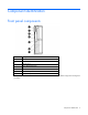
Component identification Front panel components Item Description 1 SUV connector* 2 Serial label pull tab 3 Release button 4 Server blade release lever 5 Power On/Standby button 6 Hard drive bay 1 7 Hard drive bay 2 *The SUV connector and the HP c-Class Blade SUV Cable are for some workstation blade configuration and diagnostic procedures.
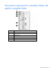
Front panel components for workstation blade with graphics expander blade Item Description 1 Serial label pull tab 2 SUV connector 3 Hard drive bay 1 4 Release button 5 Server blade release lever 6 Hard drive bay 2 Component identification 7
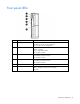
Front panel LEDs Item Description Status 1 UID LED Blue = Identified Blue flashing = Active remote management Off = No active remote management 2 Health LED Green = Normal Flashing = Booting Amber = Degraded condition Red = Critical condition 3 Flex-10 NIC 1 LED* Green = Network linked Green flashing = Network activity Off = No link or activity 4 Flex-10 NIC 1 LED* Green = Network linked Green flashing = Network activity Off = No link or activity 5 Reserved — 6 System power LED Green =
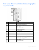
Front panel LEDs for workstation blade with graphics expansion blade Item Description Status 1 UID LED Blue = Identified Blue flashing = Active remote management Off = No active remote management 2 Health LED Green = Normal Flashing = Booting Amber = Degraded condition Red = Critical condition 3 Flex-10 NIC 1 LED* Green = Network linked Green flashing = Network activity Off = No link or activity 4 Flex-10 NIC 1 LED* Green = Network linked Green flashing = Network activity Off = No link or act
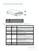
SAS and SATA hard drive LEDs Item Description 1 Fault/UID LED (amber/blue) 2 Online LED (green) SAS and SATA hard drive LED combinations Online/activity LED (green) Fault/UID LED (amber/blue) Interpretation On, off, or flashing Alternating amber and blue The drive has failed, or a predictive failure alert has been received for this drive; it also has been selected by a management application.
Online/activity LED (green) Fault/UID LED (amber/blue) Interpretation Off Steadily amber A critical fault condition has been identified for this drive, and the controller has placed it offline. Replace the drive as soon as possible. Off Amber, flashing regularly (1 Hz) A predictive failure alert has been received for this drive. Replace the drive as soon as possible. Off Off The drive is offline, a spare, or not configured as part of an array.
Mezzanine connector definitions A PCIe x8 mezzanine connector supports x16 cards at up to x8 speeds. Item PCIe Mezzanine connector 1 x8, Type I mezzanine card only Mezzanine connector 2 x8, Type 1 or II mezzanine card DIMM slot locations DIMM slots are numbered sequentially (1 through 6) for each processor. The supported AMP modes use the letter assignments for population guidelines.
HP c-Class Blade SUV Cable Item Connector Description 1 Server blade For connecting to the SUV connector on the workstation blade front panel 2 Video For connecting a video monitor 3 USB For connecting up to two USB devices 4 Serial For trained personnel to connect a null modem serial cable and perform advanced diagnostic procedures Component identification 13
Operations Power down the workstation blade Before powering down the workstation blade for any upgrade or maintenance procedures, perform a backup of critical server data and programs. IMPORTANT: When the workstation blade is in standby mode, auxiliary power is still being provided to the system. Depending on the Onboard Administrator configuration, use one of the following methods to power down the workstation blade: • Press and release the Power On/Standby button.
o poweroff server all This command initiates a controlled shutdown of applications and the OS before the workstation blade enters standby mode. o poweroff server all force This command forces the workstation blade to enter standby mode without exiting applications and the OS. This command is an emergency method to force a shutdown in the event of a hung application. • Use the Onboard Administrator GUI to initiate a shutdown: a.
Remove the access panel To remove the component: 1. Power down the workstation blade (on page 14). 2. Remove the workstation blade (on page 15). 3. Lift the access panel latch and slide the access panel to the rear. 4. Remove the access panel. WARNING: To reduce the risk of personal injury from hot surfaces, allow the drives and the internal system components to cool before touching them.
Remove the WS460c Graphics Expansion Blade access panel To remove the access panel: 1. Lift the access panel latch (1). The access panel slides to the rear (2). 2. Remove the access panel. To reinstall the access panel, follow these steps in reverse order. Remove the WS460c Graphics Expansion Blade To remove the blade: 1. Remove the WS460c Graphics Expansion Blade access panel (on page 17). 2. Disconnect the four PCIe/SAS cables from the PCIe riser board, noting the location for reinstallation. 3.
4. To remove the graphics expansion blade from the workstation blade, carefully pull up on the front and right sides of the PCIe card cage to disengage it from the anchoring pins on the expansion blade enclosure (1), and then lift the PCIe card cage out of the expansion blade enclosure (2). To reinstall the blade, follow these steps in reverse order.
3. If you are removing the graphics card from the PCIe card cage, disconnect the power cables from the graphics board. 4. Remove the two Torx-15 screws that secure the front of the PCIe card cage (1). 5. Carefully pull up on the front and right sides of the PCIe card cage to disengage it from the anchoring pins on the expansion blade enclosure, and then lift the PCIe card cage out of the expansion blade enclosure (2).
1. Place the host bus adapter (1) into mezzanine slot one, and then tighten the screws (2). 2. Place the expansion cable card (1) into mezzanine slot two, and then tighten the screw (2).
3. Slide the graphics expansion blade onto the workstation blade. 4. Remove the screws (1), and then remove the PCIe slot card (2) from the graphics expansion blade.
5. Insert the graphic card into PCIe slot one. 6. Replace the graphic card retainer.
7. Locate the dipswitch on the left side of the PCIe slot card, and then flip switch 2 to ON. 8. Replace the PCIe slot card on the graphics expansion blade (1), and then tighten the screws (2).
9. Insert the graphic card power cable. 10. Insert cables into the graphic expansion cable mezzanine card.
11. Insert cable 4 to slot 2 (1), and then insert cable 3 to slot 1 (2). 12. Slide the cover onto graphic expansion blade.
Setup Overview Installation of a workstation blade requires the following steps: 1. Install and configure an HP BladeSystem c-Class enclosure. 2. Install any workstation blade options. 3. Install interconnect modules in the enclosure. 4. Connect the interconnect modules to the network. 5. Install a workstation blade. 6. Complete the workstation blade configuration. 7. Install any software as outlined in the workstation blade Windows or Linux Administrator's Guide.
Two types of interconnect modules are available for HP BladeSystem c-Class enclosures: Pass-Thru modules and switch modules. For more information about interconnect module options, see the HP website (http://www.hp.com/go/bladesystem/interconnects). IMPORTANT: To connect to a network with a Pass-Thru module, always connect the Pass-Thru module to a network device that supports Gigabit speed.
2. If you are installing a workstation blade, remove the enclosure cover as shown in the following figure. If you are installing a workstation blade with the graphics expansion blade, remove the enclosure covers. 3. If you are installing the workstation blade, prepare it for installation.
4. If you are installing the workstation blade with the graphics expansion blade, prepare it for installation. 5. Install the workstation blade, as shown in the following figure, or the workstation blade with the graphics expansion blade.
Hardware options installation Introduction If more than one option is being installed, read the installation instructions for all the hardware options and identify similar steps to streamline the installation process. WARNING: To reduce the risk of personal injury from hot surfaces, allow the drives and the internal system components to cool before touching them. CAUTION: To prevent damage to electrical components, properly ground the server before beginning any installation procedure.
2. Prepare the hard drive. 3. Install the hard drive. 4. Determine the status of the drive from the hot-plug SAS hard drive LED combinations ("SAS and SATA hard drive LED combinations" on page 10). Processor option WARNING: To reduce the risk of personal injury from hot surfaces, allow the drives and the internal system components to cool before touching them.
IMPORTANT: Processor socket 1 must always be populated. If processor socket 1 is empty, the workstation blade does not power up. Before installing a processor, you must remove any previously installed WS460c Graphics Expansion Blade access panel and blade. To install the component: 1. Update the system ROM using any standard ROM flash mechanism. 2. Power down the workstation blade (on page 14). 3. Remove the workstation blade (on page 15). 4. Remove the access panel (on page 16). 5.
7. Open the processor locking lever and the processor socket retaining bracket. Do not remove the processor socket cover. IMPORTANT: Be sure the processor remains inside the processor installation tool. 8. If the processor has separated from the installation tool, carefully re-insert the processor in the tool. Handle the processor by the edges only, and do not touch the bottom of the processor, especially the contact area.
9. Align the processor installation tool with the socket, and then install the processor. THE PINS ON THE SYSTEM BOARD ARE VERY FRAGILE AND EASILY DAMAGED. CAUTION: THE PINS ON THE SYSTEM BOARD ARE VERY FRAGILE AND EASILY DAMAGED. To avoid damage to the system board: • Never install or remove a processor without using the processor installation tool. • Do not touch the processor socket contacts. • Do not tilt or slide the processor when lowering the processor into the socket.
10. Press the tabs on the processor installation tool to separate it from the processor, and then remove the tool. 11. Close the processor socket retaining bracket and the processor locking lever. The processor socket cover is automatically ejected. Remove the cover. CAUTION: Be sure to close the processor socket retaining bracket before closing the processor locking lever. The lever should close without resistance.
Memory options IMPORTANT: This workstation blade does not support mixing RDIMMs and UDIMMs. Attempting to mix these two types causes the server to halt during BIOS initialization. The memory subsystem in this workstation blade can support RDIMMs or UDIMMs. Both types are referred to as DIMMs when the information applies to both types. When specified as RDIMM or UDIMM, the information applies to that type only. All memory installed in the workstation blade must be the same type.
DIMM identification To determine DIMM characteristics, use the label attached to the DIMM and the following illustration and table. Item Description Definition 1 Size — 2 Rank 1R = Single-rank 2R = Dual-rank 4R = Quad-rank 3 Data width x4 = 4-bit x8 = 8-bit 4 Voltage rating L = Low voltage (1.
Advanced Memory Protection options are configured in RBSU. If the requested AMP mode is not supported by the installed DIMM configuration, the workstation blade boots in Advanced ECC mode. For more information, see "HP ROM-Based Setup Utility (on page 56)." For the latest memory configuration information, see the QuickSpecs on the HP website (http://www.hp.com). RDIMM maximum memory configurations The following table lists the maximum memory configuration possible with 8-GB RDIMMs.
General DIMM slot population guidelines Observe the following guidelines for all AMP modes: • Populate DIMM slots for a processor only if the processor is installed. • To maximize performance in multi-processor configurations, distribute the total memory capacity between all processors as evenly as possible. • Do not mix Unbuffered and Registered PC3 DIMMs. • Each channel supports up to two Unbuffered DIMMs.
• Always install DIMMs in channels 1 and 2 for each installed processor. • Do not install DIMMs in channel 3 for any processor. • DIMMs installed on channel 1 and channel 2 of an installed processor must be identical. • In multi-processor configurations, each processor must have a valid Mirrored Memory configuration. • In multi-processor configurations, each processor may have a different valid Mirrored Memory configuration.
• Do not install DIMMs in channel 3 for any processor. • DIMM configuration on channel 1 and channel 2 of a processor must be identical. • In multiprocessor configurations, each processor must have a valid Lockstep Memory configuration. • In multiprocessor configurations, each processor may have a different valid Lockstep Memory configuration.
Before installing a DIMM, you must remove any previously installed WS460c Graphics Expansion Blade access panel and blade ("Remove the WS460c Graphics Expansion Blade" on page 17). To install a DIMM: 1. Power down the server ("Power down the workstation blade" on page 14). 2. Remove the workstation blade (on page 15). 3. Remove the access panel (on page 16). 4. Remove all DIMM baffles ("Remove the DIMM baffle" on page 16). 5. Open the DIMM slot latches. 6. Install the DIMM. 7.
5. Remove hard drives. 6. Remove the hard drive backplane. 7. Remove the two T-15 screws from the front panel and hard drive cage assembly. 8. Remove the front panel and hard drive cage assembly.
9. Connect the BBWC battery pack cable to the cache module. 10. Install the cache module. 11. Route the BBWC battery pack cable.
12. Install the battery pack. 13. Install the front panel and hard drive cage assembly. 14. Install the two T-15 screws to secure the front panel and hard drive cage assembly to the chassis.
15. Install the hard drive backplane. Press down on the hard drive backplane retainer to seat the board. 16. Install the hard drives. 17. Install the access panel. 18. If necessary, reinstall the WS460c Graphics Expansion Blade ("Remove the WS460c Graphics Expansion Blade" on page 17) and the access panel ("Remove the WS460c Graphics Expansion Blade access panel" on page 17).
Cabling BBWC battery pack cabling • Cache module cabling: Use the 24-inch BBWC battery pack cable. Using the HP c-Class Blade SUV Cable The HP c-Class Blade SUV Cable enables the user to perform workstation blade administration, configuration, and diagnostic procedures by connecting video and USB devices directly to the workstation blade. For SUV cable connectors, see "HP c-Class Blade SUV Cable (on page 13).
CAUTION: Before disconnecting the SUV cable from the connector, always squeeze the release buttons on the sides of the connector. Failure to do so can result in damage to the equipment. 1. Connect the SUV cable to the workstation blade. 2. Connect the video connector to a monitor. 3. Connect a USB mouse to one USB connector. 4. Connect a USB keyboard to the second USB connector.
o USB diskette drive Item Description 1 Monitor 2 USB CD/DVD-ROM drive or diskette drive 3 USB keyboard 4 USB hub 5 USB mouse 6 HP c-Class Blade SUV Cable Cabling 49
Software and configuration utilities Server blade deployment tools Software drivers and additional components HP offers the following additional software components for workstation blades: • Health and Wellness driver and IML viewer • iLO 2 Management interface driver • Rack infrastructure interface service For Microsoft® Windows® OS users, these items are included in the HP ProLiant iLO 2 Standard Blade Edition, available from the HP website (http://www.hp.com/servers/lights-out).
To connect to the workstation blade using iLO 2, install the workstation blade in an enclosure. Onboard Administrator assigns an IP address to enable iLO 2 connectivity to the workstation blade. The c-Class tab enables you to control specific settings for the HP BladeSystem. iLO 2 also provides web-based status for the HP BladeSystem configuration. For detailed information about iLO 2, refer to the HP Integrated Lights-Out User Guide on the HP website (http://www.hp.com/servers/lights-out).
NOTE: Actual NIC numeration depends on several factors, including the OS installed on the workstation blade. HP recommends using one of the following methods for PXE deployment: • HP Insight Control server deployment • SmartStart Scripting Toolkit (on page 52) HP Insight Control server deployment NOTE: To deploy workstation blades in an existing server blade enclosure, always use the most recent version of HP Insight Control server deployment available at the HP website (http://www.hp.com).
o Microsoft® Internet Explorer 5.5 or above with 128-bit encryption o Ethernet NIC with 10/100 RJ-45 connector o TCP/IP networking and an IP address compatible with one of the following: the iLO 2 Diagnostic Port IP address or an assigned DHCP or static IP address o CD-ROM drive, CD/DVD-ROM drive, and/or diskette drive o Any of the following Java™ Runtime Environment versions: 1.3.1_02 1.3.1_07 1.3.1_08 1.4.1 for Windows® users only 1.4.
Access the Java™ Runtime Environment versions at the HP website (http://java.sun.com/products/archive/index.html). • Network server with an OS installed CD-ROM deployment CD-ROM deployment involves using a bootable CD that executes scripts to configure the hardware and install the OS. After the OS is configured, the workstation blade can access the network to locate the scripts and files necessary for deployment. Before beginning the deployment process, connect the workstation blade to the network.
Two methods are available for diskette image deployment: • iLO virtual floppy (on page 55) • PXE Some USB floppy disk drives do not work when you press F6 to install mass storage drivers during the Windows XP installation process. For more information, see http://support.microsoft.com/kb/916196/en-us (http://support.microsoft.com/kb/916196/en-us). Creating a boot diskette The SmartStart Scripting Toolkit provides the tools and information for creating a boot diskette.
• The server blade enclosure management module firmware is up-to-date. See the HP Business Support Center website (http://www.hp.com/support). • The workstation blade is cabled properly to a supported SAN. • SAN storage drivers are loaded. See supporting white papers and the HP website (http://www.hp.com). For SAN configuration information for the workstation blade, see the HP StorageWorks SAN Design Reference Guide on the HP website (http://h18000.www1.hp.com/products/storageworks/san/documentation.
Auto-configuration process The auto-configuration process automatically runs when you boot the server for the first time. During the power-up sequence, the system ROM automatically configures the entire system without needing any intervention. During this process, the ORCA utility, in most cases, automatically configures the array to a default setting based on the number of drives connected to the server. NOTE: The server may not support all the following examples.
Configuring mirrored memory To configure mirrored memory: 1. Install the required DIMMs. 2. Access RBSU by pressing the F9 key during power-up when the prompt is displayed. 3. Select System Options. 4. Select Advanced Memory Protection. 5. Select Mirrored Memory with Advanced ECC Support. 6. Press the Enter key. 7. Press the Esc key to exit the current menu or press the F10 key to exit RBSU. For more information on mirrored memory, see the white paper on the HP website (http://h18000.www1.hp.
• Mozilla Firefox 2.0 or later For Linux servers, see the README.TXT file for additional browser and support information. For more information about the controller and its features, see the HP Smart Array Controllers for HP ProLiant Servers User Guide on the HP website (http://www.hp.com/support/SAC_UG_ProLiantServers_en). To configure arrays, see the Configuring Arrays on HP Smart Array Controllers Reference Guide on the HP website (http://www.hp.com/support/CASAC_RG_en).
Management tools Automatic Server Recovery ASR is a feature that causes the system to restart when a catastrophic operating system error occurs, such as a blue screen, ABEND (does not apply to HP ProLiant DL980 Servers), or panic. A system fail-safe timer, the ASR timer, starts when the System Management driver, also known as the Health Driver, is loaded. When the operating system is functioning properly, the system periodically resets the timer.
Erase Utility CAUTION: Perform a backup before running the System Erase Utility. The utility sets the system to its original factory state, deletes the current hardware configuration information, including array setup and disk partitioning, and erases all connected hard drives completely. Refer to the instructions for using this utility.
NOTE: The server ships with the same version programmed on each side of the ROM. Safety and security benefits When you flash the system ROM, ROMPaq writes over the backup ROM and saves the current ROM as a backup, enabling you to switch easily to the alternate ROM version if the new ROM becomes corrupted for any reason. This feature protects the existing ROM version, even if you experience a power failure while flashing the ROM.
Diagnostic tools HP Insight Diagnostics HP Insight Diagnostics is a proactive workstation blade management tool, available in both offline and online versions, that provides diagnostics and troubleshooting capabilities to assist IT administrators who verify workstation blade installations, troubleshoot problems, and perform repair validation. HP Insight Diagnostics Offline Edition performs various in-depth system and component testing while the OS is not running.
• From within HP Insight Diagnostics (on page 63) For more information, see the Management CD or DVD in the HP Insight Foundation suite for ProLiant. Array Diagnostic Utility The HP Array Diagnostics Utility is a web-based application that creates a report of all HP storage controllers and disk drives. This report provides vital information to assist in identifying faults or conditions that may require attention. ADU can be accessed from the SmartStart CD or downloaded from the HP website (http://www.hp.
Keeping the system current ProLiant Support Packs PSPs represent operating system-specific bundles of ProLiant optimized drivers, utilities, and management agents. Refer to the PSP website (http://h18000.www1.hp.com/products/servers/management/psp.html). NOTE: The SAS/SATA controller driver in the PSP for the WS460c G6 workstation blade is currently an unsigned driver. The driver packaging in the PSP prevents the unsigned warning message from appearing.
HP Smart Update Manager The HP Smart Update Manager provides intelligent and flexible firmware and software deployment. This technology assists in reducing the complexity of provisioning and updating HP ProLiant Servers, options, and Blades within the data center. HP SUM is delivered on the Smart Update Firmware DVD, ProLiant Support Packs, and Easy Set-up CDs. HP SUM enables system administrators to upgrade ROM images efficiently across a wide range of workstation blades and options.
Troubleshooting Troubleshooting resources The HP ProLiant Servers Troubleshooting Guide provides procedures for resolving common problems and comprehensive courses of action for fault isolation and identification, error message interpretation, issue resolution, and software maintenance on ProLiant servers and server blades. This guide includes problem-specific flowcharts to help you navigate complex troubleshooting processes. To view the guide, select a language: • English (http://www.hp.
Important safety information Before servicing this product, read the Important Safety Information document provided with the server. Symbols on equipment The following symbols may be placed on equipment to indicate the presence of potentially hazardous conditions. This symbol indicates the presence of hazardous energy circuits or electric shock hazards. Refer all servicing to qualified personnel. WARNING: To reduce the risk of injury from electric shock hazards, do not open this enclosure.
WARNING: To reduce the risk of personal injury or damage to the equipment, be sure that: • • • • • The leveling feet are extended to the floor. The full weight of the rack rests on the leveling feet. The stabilizing feet are attached to the rack if it is a single-rack installation. The racks are coupled together in multiple-rack installations. Only one component is extended at a time. A rack may become unstable if more than one component is extended for any reason.
Version Control Agent. The VCA gives you a list of names and versions of all installed HP drivers, Management Agents, and utilities, and whether they are up-to-date. o HP recommends you have access to the server documentation for server-specific information. o HP recommends you have access to the SmartStart CD for value-added software and drivers required during the troubleshooting process. Download the current version of SmartStart from the HP website (http://www.hp.com/servers/smartstart).
Before removing the components, be sure to determine the minimum configuration for each component and follow all guidelines in the server user guide. Always use the recommended minimum configuration above before removing any processors. If you are unable to isolate the issue with the configuration above, you will then remove all but one of the processors.
Troubleshooting flowcharts To effectively troubleshoot a problem, HP recommends that you start with the first flowchart in this section, "Start diagnosis flowchart (on page 72)," and follow the appropriate diagnostic path. If the other flowcharts do not provide a troubleshooting solution, follow the diagnostic steps in "General diagnosis flowchart (on page 73).
General diagnosis flowchart The General diagnosis flowchart provides a generic approach to troubleshooting. If you are unsure of the problem, or if the other flowcharts do not fix the problem, use the following flowchart.
Item See 4 The most recent version of a particular server blade or option firmware is available on the HP Support website (http://www.hp.com/support). 5 "General memory problems are occurring" in the HP ProLiant Servers Troubleshooting Guide located on the Documentation CD or see "Troubleshooting resources (on page 67)" 6 • • 7 • • • Maintenance and service guides for p-Class server blades, located on the Documentation CD or the HP website (http://www.hp.
Server blade power-on problems flowchart Symptoms: • The server does not power on. • The system power LED is off or amber.
• The health LED is red or amber. NOTE: For the location of server LEDs and information on their statuses, refer to the server documentation.
POST problems flowchart Symptoms: • Server does not complete POST NOTE: The server has completed POST when the system attempts to access the boot device.
Item See 1 Server blade power-on problems flowchart (on page 75) 2 "POST error messages and beep codes (on page 83)" 3 "Video problems" in the HP ProLiant Servers Troubleshooting Guide located on the Documentation CD or see "Troubleshooting resources (on page 67)" 4 "General memory problems are occurring" in the HP ProLiant Servers Troubleshooting Guide located on the Documentation CD or see "Troubleshooting resources (on page 67)" 5 "Breaking the server down to the minimum hardware configuration
OS boot problems flowchart There are two ways to use SmartStart when diagnosing OS boot problems on a server blade: • Use iLO to remotely attach virtual devices to mount the SmartStart CD onto the server blade. • Use a local I/O cable and drive to connect to the server blade, and then restart the server blade.
Possible causes: • Corrupted OS • Hard drive subsystem problem • Incorrect boot order setting in RBSU Item See 1 HP ROM-Based Setup Utility User Guide (http://www.hp.
* See the server blade OS boot problems flowchart (on page 79) Server fault indications flowchart Symptoms: • Server boots, but a fault event is reported by Insight Management Agents (on page 61) • Server boots, but the internal health LED, external health LED, or component health LED is red or amber Troubleshooting 81
NOTE: For the location of server LEDs and information on their statuses, refer to the server documentation.
POST error messages and beep codes Introduction to POST error messages The error messages and codes in this section include all new messages generated by this workstation blade. Some messages are informational and do not indicate an error. A workstation blade generates only the codes that are applicable to its configuration and options.
For a complete listing of error messages, refer to the "POST error messages" in the HP ProLiant Servers Troubleshooting Guide located on the Documentation CD or on the HP website (http://www.hp.com/support). WARNING: To avoid potential problems, ALWAYS read the warnings and cautionary information in the server documentation before removing, replacing, reseating, or modifying system components.
Battery replacement If the workstation blade no longer automatically displays the correct date and time, you may need to replace the battery that provides power to the real-time clock. Under normal use, battery life is 5 to 10 years. WARNING: The computer contains an internal lithium manganese dioxide, a vanadium pentoxide, or an alkaline battery pack. A risk of fire and burns exists if the battery pack is not properly handled.
6. Remove the battery. IMPORTANT: Replacing the system board battery resets the system ROM to its default configuration. After replacing the battery, reconfigure the system through RBSU. To replace the component, reverse the removal procedure. If necessary, reinstall the WS460c Graphics Expansion Blade and the access panel. For more information about battery replacement or proper disposal, contact an authorized reseller or an authorized service provider.
Regulatory compliance notices Regulatory compliance identification numbers For the purpose of regulatory compliance certifications and identification, this product has been assigned a unique regulatory model number. The regulatory model number can be found on the product nameplate label, along with all required approval markings and information. When requesting compliance information for this product, always refer to this regulatory model number.
radio communications. However, there is no guarantee that interference will not occur in a particular installation. If this equipment does cause harmful interference to radio or television reception, which can be determined by turning the equipment off and on, the user is encouraged to try to correct the interference by one or more of the following measures: • Reorient or relocate the receiving antenna. • Increase the separation between the equipment and receiver.
This Class A digital apparatus meets all requirements of the Canadian Interference-Causing Equipment Regulations. Cet appareil numérique de la classe A respecte toutes les exigences du Règlement sur le matériel brouilleur du Canada. Class B equipment This Class B digital apparatus meets all requirements of the Canadian Interference-Causing Equipment Regulations. Cet appareil numérique de la classe B respecte toutes les exigences du Règlement sur le matériel brouilleur du Canada.
This symbol on the product or on its packaging indicates that this product must not be disposed of with your other household waste. Instead, it is your responsibility to dispose of your waste equipment by handing it over to a designated collection point for the recycling of waste electrical and electronic equipment.
Class B equipment Chinese notice Class A equipment Vietnam compliance marking notice This marking is for applicable products only. Laser compliance This product may be provided with an optical storage device (that is, CD or DVD drive) and/or fiber optic transceiver. Each of these devices contains a laser that is classified as a Class 1 Laser Product in accordance with US FDA regulations and the IEC 60825-1. The product does not emit hazardous laser radiation. Each laser product complies with 21 CFR 1040.
WARNING: The computer contains an internal lithium manganese dioxide, a vanadium pentoxide, or an alkaline battery pack. A risk of fire and burns exists if the battery pack is not properly handled. To reduce the risk of personal injury: • Do not attempt to recharge the battery. • Do not expose the battery to temperatures higher than 60°C (140°F). • Do not disassemble, crush, puncture, short external contacts, or dispose of in fire or water.
Electrostatic discharge Preventing electrostatic discharge To prevent damaging the system, be aware of the precautions you need to follow when setting up the system or handling parts. A discharge of static electricity from a finger or other conductor may damage system boards or other static-sensitive devices. This type of damage may reduce the life expectancy of the device. To prevent electrostatic damage: • Avoid hand contact by transporting and storing products in static-safe containers.
Specifications Environmental specifications Specification Value — Temperature range* Operating 10°C to 35°C (50°F to 95°F) Non-operating -30°C to 60°C (-22°F to 140°F) Relative humidity (noncondensing)** — Operating 10% to 90% @ 28°C (82.4°F) Non-operating 5% to 95% @ 38.7°C (101.7°F) Altitude† — Operating 3050 m (10,000 ft) Non-operating 9144 m (30,000 ft) * The following temperature conditions and limitations apply: - All temperature ratings shown are for sea level.
Support and other resources Before you contact HP Be sure to have the following information available before you call HP: • Active Health System log Download and have available an Active Health System log for 3 days before the failure was detected. For more information, see the HP iLO 4 User Guide or HP Intelligent Provisioning User Guide on the HP website (http://www.hp.com/go/ilo/docs).
providers or service partners) identifies that the repair can be accomplished by the use of a CSR part, HP will ship that part directly to you for replacement. There are two categories of CSR parts: • Mandatory—Parts for which customer self repair is mandatory. If you request HP to replace these parts, you will be charged for the travel and labor costs of this service. • Optional—Parts for which customer self repair is optional. These parts are also designed for customer self repair.
Pour plus d'informations sur le programme CSR de HP, contactez votre Mainteneur Agrée local. Pour plus d'informations sur ce programme en Amérique du Nord, consultez le site Web HP (http://www.hp.com/go/selfrepair). Riparazione da parte del cliente Per abbreviare i tempi di riparazione e garantire una maggiore flessibilità nella sostituzione di parti difettose, i prodotti HP sono realizzati con numerosi componenti che possono essere riparati direttamente dal cliente (CSR, Customer Self Repair).
HINWEIS: Einige Teile sind nicht für Customer Self Repair ausgelegt. Um den Garantieanspruch des Kunden zu erfüllen, muss das Teil von einem HP Servicepartner ersetzt werden. Im illustrierten Teilekatalog sind diese Teile mit „No“ bzw. „Nein“ gekennzeichnet. CSR-Teile werden abhängig von der Verfügbarkeit und vom Lieferziel am folgenden Geschäftstag geliefert. Für bestimmte Standorte ist eine Lieferung am selben Tag oder innerhalb von vier Stunden gegen einen Aufpreis verfügbar.
sustituciones que lleve a cabo el cliente, HP se hará cargo de todos los gastos de envío y devolución de componentes y escogerá la empresa de transporte que se utilice para dicho servicio. Para obtener más información acerca del programa de Reparaciones del propio cliente de HP, póngase en contacto con su proveedor de servicios local. Si está interesado en el programa para Norteamérica, visite la página web de HP siguiente (http://www.hp.com/go/selfrepair).
Opcional – Peças cujo reparo feito pelo cliente é opcional. Essas peças também são projetadas para o reparo feito pelo cliente. No entanto, se desejar que a HP as substitua, pode haver ou não a cobrança de taxa adicional, dependendo do tipo de serviço de garantia destinado ao produto. OBSERVAÇÃO: Algumas peças da HP não são projetadas para o reparo feito pelo cliente. A fim de cumprir a garantia do cliente, a HP exige que um técnico autorizado substitua a peça.
Support and other resources 101
Support and other resources 102
Acronyms and abbreviations ABEND abnormal end ACU Array Configuration Utility ADU Array Diagnostics Utility AMP Advanced Memory Protection ASR Automatic Server Recovery BBWC battery-backed write cache BMC baseboard management controller iLO 2 Integrated Lights-Out 2 IML Integrated Management Log ORCA Option ROM Configuration for Arrays POST Power-On Self Test PXE preboot execution environment Acronyms and abbreviations 103
RBSU ROM-Based Setup Utility SAS serial attached SCSI SATA serial ATA SIM Systems Insight Manager UID unit identification USB universal serial bus VCA Version Control Agent Acronyms and abbreviations 104
Documentation feedback HP is committed to providing documentation that meets your needs. To help us improve the documentation, send any errors, suggestions, or comments to Documentation Feedback (mailto:docsfeedback@hp.com). Include the document title and part number, version number, or the URL when submitting your feedback.
Index A access panel 15 acoustics statement for Germany 91 ACU (Array Configuration Utility) 57 additional information 66 ADU (Array Diagnostic Utility) 63 Advanced ECC memory 37, 38 Array Configuration Utility (ACU) 57 Array Diagnostic Utility (ADU) 63 ASR (Automatic Server Recovery) 59 authorized reseller 94 auto-configuration process 56 Automatic Server Recovery (ASR) 59 B Basic Input/Output System (BIOS) 56, 59 batteries, replacing 84, 90 battery 10, 90 battery replacement notice 90 BBWC (battery-backe
drives 9, 10, 29 E electrostatic discharge 92 enclosure connector 10 environmental specifications Erase Utility 60 error messages 82 European Union notice 88 external cables 46 93 I F FCC (Federal Communications Commission) notice 86, 87 FCC rating label 86 features 6 Federal Communications Commission (FCC) notice 86, 87 firmware upgrade utility, troubleshooting 66 flowcharts 71, 72, 74, 76, 78, 80 front panel buttons 6, 7 front panel components 6, 7 front panel LEDs 7, 8 G general diagnosis flowchart
lockstep memory loose connections processors 10, 69 Product ID 58 ProLiant Support Pack (PSP) 64 PSP (ProLiant Support Pack) 64 PSPs, overview 64 PXE (preboot execution environment) PXE deployment 50 37, 39, 57 70 M maintenance guidelines 64 Management Agents 60 management tools 49, 59 memory 35, 36, 57 memory configurations 36 memory options 29 memory subsystem architecture 35 memory, mirrored 37, 38, 57 mezzanine board connectors 10 mezzanine connectors 10, 11 mirrored memory 37, 38, 57 modifications,
setting up a network 50 setup 25 Smart Update Manager 65 SmartStart Scripting Toolkit 51 software components 49 specifications 93 specifications, environmental 93 specifications, server blade 93 standards 86 start diagnosis flowchart 71 static electricity 92 StorageWorks Library and Tape Tools (L&TT) support 63, 94 supported operating systems 64 SUV connector 6, 12, 46 symbols on equipment 67 symptom information 68 system board 10 system board battery 10, 90 system board thumbscrews 10 system components 6 s