HP ProLiant WS460c Gen8 Graphics Server Blade and Expansion Blade Maintenance and Service Guide Abstract This guide describes identification and maintenance procedures, diagnostic tools, specifications and requirements for hardware components and software. This guide is for an experienced service technician. HP assumes you are qualified in the servicing of computer equipment, trained in recognizing hazards in products, and are familiar with weight and stability precautions.
© Copyright 2012, 2014 Hewlett-Packard Development Company, L.P. The information contained herein is subject to change without notice. The only warranties for HP products and services are set forth in the express warranty statements accompanying such products and services. Nothing herein should be construed as constituting an additional warranty. HP shall not be liable for technical or editorial errors or omissions contained herein. Microsoft® and Windows® are U.S.
Contents Customer self repair ...................................................................................................................... 5 Parts only warranty service ......................................................................................................................... 5 Illustrated parts catalog ............................................................................................................... 15 Server blade components ...........................................
System board ......................................................................................................................................... 78 Server blade release lever assembly .......................................................................................................... 83 HP Trusted Platform Module ...................................................................................................................... 87 Quadro 500M, 1000M, and 3000M graphics cards ..................
Customer self repair HP products are designed with many Customer Self Repair (CSR) parts to minimize repair time and allow for greater flexibility in performing defective parts replacement. If during the diagnosis period HP (or HP service providers or service partners) identifies that the repair can be accomplished by the use of a CSR part, HP will ship that part directly to you for replacement. There are two categories of CSR parts: • Mandatory—Parts for which customer self repair is mandatory.
Obligatoire - Pièces pour lesquelles la réparation par le client est obligatoire. Si vous demandez à HP de remplacer ces pièces, les coûts de déplacement et main d'œuvre du service vous seront facturés. Facultatif - Pièces pour lesquelles la réparation par le client est facultative. Ces pièces sont également conçues pour permettre au client d'effectuer lui-même la réparation.
In base alla disponibilità e alla località geografica, le parti CSR vengono spedite con consegna entro il giorno lavorativo seguente. La consegna nel giorno stesso o entro quattro ore è offerta con un supplemento di costo solo in alcune zone. In caso di necessità si può richiedere l'assistenza telefonica di un addetto del centro di supporto tecnico HP. Nel materiale fornito con una parte di ricambio CSR, HP specifica se il cliente deve restituire dei componenti.
defekte Teil nicht zurückschicken, kann HP Ihnen das Ersatzteil in Rechnung stellen. Im Falle von Customer Self Repair kommt HP für alle Kosten für die Lieferung und Rücksendung auf und bestimmt den Kurier-/Frachtdienst. Weitere Informationen über das HP Customer Self Repair Programm erhalten Sie von Ihrem Servicepartner vor Ort. Informationen über das CSR-Programm in Nordamerika finden Sie auf der HP Website unter (http://www.hp.com/go/selfrepair).
enviara el componente defectuoso requerido, HP podrá cobrarle por el de sustitución. En el caso de todas sustituciones que lleve a cabo el cliente, HP se hará cargo de todos los gastos de envío y devolución de componentes y escogerá la empresa de transporte que se utilice para dicho servicio. Para obtener más información acerca del programa de Reparaciones del propio cliente de HP, póngase en contacto con su proveedor de servicios local.
Neem contact op met een Service Partner voor meer informatie over het Customer Self Repair programma van HP. Informatie over Service Partners vindt u op de HP website (http://www.hp.com/go/selfrepair). Garantieservice "Parts Only" Het is mogelijk dat de HP garantie alleen de garantieservice "Parts Only" omvat. Volgens de bepalingen van de Parts Only garantieservice zal HP kosteloos vervangende onderdelen ter beschikking stellen.
No caso desse serviço, a substituição de peças CSR é obrigatória. Se desejar que a HP substitua essas peças, serão cobradas as despesas de transporte e mão-de-obra do serviço.
Customer self repair 12
Customer self repair 13
Customer self repair 14
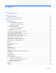
Illustrated parts catalog Server blade components Item Description Spare part number Customer self repair (on page 5) Mechanical components 1 Access panel 670024-001 Mandatory1 2 Drive blank 670033-001 Mandatory1 3 Front panel/drive cage assembly 670025-001 Mandatory1 4 DIMM baffles — — a) Standard DIMM baffle, right 670028-001 Mandatory1 b) Standard DIMM baffle, left, with T-15 Torx screwdriver and 670029-001 DIMM tool c) Non-standard (tall) Three-Rank DIMM baffle, right* 709381-001
Item Description Spare part number Customer self repair (on page 5) d) Mezzanine assembly guide pins (2) — — e) T-15 system board screws (2) — — Processors — — a) 1.80-GHz Intel Xeon E5-2603 processor** 670533-001 Optional2 b) 1.80-GHz Intel Xeon E5-2603 v2 processor* ** 730243-001 Optional2 c) 2.40-GHz Intel Xeon E5-2609 processor* ** 670530-001 Optional2 d) 2.40-GHz Intel Xeon E5-2609 v2 processor* ** 730242-001 Optional2 e) 2.
Item 9 10 11 Description Spare part number Customer self repair (on page 5) ff) 2.40-GHz Intel Xeon E5-2695 v2 processor* ** 730246-001 Optional2 gg) 2.
Item Description Spare part number Customer self repair (on page 5) Boards DIMMs — — a) 32-GB, Quad Rank x4 PC3L-10600L (DDR3-1333) 664693-001 Mandatory1 b) 32-GB, Quad Rank x4 PC3-14900L (DDR3-1866)* 715275-001 Mandatory1 c) 24-GB, Three Rank x4 PC3L-10600R (DDR3-1333), non-standard (tall) height* d) 24-GB, Three Rank x4 PC3L-10600R (DDR3-1333), standard height* d) 16-GB, Dual Rank x4 PC3-12800R (DDR3-1333)* 707301-001 Mandatory1 718689-001 Mandatory1 684031-001 Mandatory1 e) 16-GB, Dua
Item 16 Description Spare part number Customer self repair (on page 5) c) System board (with Intel Xeon 2600 processor support) 704709-001 Optional2 d) System board (with Intel Xeon 2600 processor and Intel Xeon 2600 v2 processor support) Trusted Platform Module* 738239-001 Optional2 505836-001 No3 Optional2 Miscellaneous 17 System battery* 234556-001 18 Network adapters — — a) HP FlexFabric 10Gb 2-port 554M Adapter* 649870-001 Mandatory1 b) HP Flex-10 10Gb 2-port 530M Adapter* 65713
Mandatory: Obbligatorie—Parti che devono essere necessariamente riparate dal cliente. Se il cliente ne affida la riparazione ad HP, deve sostenere le spese di spedizione e di manodopera per il servizio. 2 Optional: Opzionali—Parti la cui riparazione da parte del cliente è facoltativa. Si tratta comunque di componenti progettati per questo scopo. Se tuttavia il cliente ne richiede la sostituzione ad HP, potrebbe dover sostenere spese addizionali a seconda del tipo di garanzia previsto per il prodotto.
Illustrated parts catalog 21
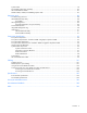
Graphics Expansion Blade components Parts listed here are in addition to parts listed for the workstation blade.
Item Description Spare part number Customer self repair (on page 5) 16 NVIDIA Quadro 1000M graphics card (MXM only)* NVIDIA Quadro 3000M graphics card (MXM only)* NVIDIA Quadro K3100M Mezzanine FIO Graphics Kit* HP MultiGPU Carrier 3 NV K3100M FIO Kit* 729352-001 No3 729353-001 No3 753269-001 No3 753112-001 No3 17 18 19 HP Multi-GPU Carrier Card* 716553-001 No3 20 *Not shown 1 Mandatory—Parts for which customer self repair is mandatory.
No: No—Algunos componentes no están diseñados para que puedan ser reparados por el usuario. Para que el usuario haga valer su garantía, HP pone como condición que un proveedor de servicios autorizado realice la sustitución de estos componentes. Dichos componentes se identifican con la palabra “No” en el catálogo ilustrado de componentes. 3 Mandatory: Verplicht—Onderdelen waarvoor Customer Self Repair verplicht is.
Removal and replacement procedures Required tools You need the following items for some procedures: • DIMM tool (provided on the DIMM baffle) • T-15 Torx screwdriver (provided on the DIMM baffle) • T-10 Torx screwdriver (not provided with the workstation blade) • HP Insight Diagnostics software ("HP Insight Diagnostics" on page 89) Safety considerations Before performing service procedures, review all the safety information.
CAUTION: When performing non-hot-plug operations, you must power down the server blade and/or the system. However, it may be necessary to leave the server blade powered up when performing other operations, such as hot-plug installations or troubleshooting. Symbols on equipment The following symbols may be placed on equipment to indicate the presence of potentially hazardous conditions. This symbol indicates the presence of hazardous energy circuits or electric shock hazards.
IMPORTANT: When the workstation blade is in standby mode, auxiliary power is still being provided to the system. Depending on the Onboard Administrator configuration, use one of the following methods to power down the workstation blade: • Press and release the Power On/Standby button. This method initiates a controlled shutdown of applications and the OS before the workstation blade enters standby mode.
b. On the Virtual Power menu, to initiate a controlled shutdown of applications and the OS, select Momentary Press, or to initiate an emergency shutdown of applications and the OS, select Press and Hold. Remove the workstation blade To remove the component: 1. Identify the proper workstation blade. 2. Power down the workstation blade (on page 26). 3. Remove the workstation blade. 4. Place the workstation blade on a flat, level work surface.
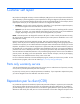
2. Slide the access panel forward until it clicks into place. WS460c Graphics Expansion Blade access panel To remove the component: 1. Power down the workstation blade (on page 26). 2. Remove the workstation blade (on page 28). 3. Lift the access panel latch (1), and then slide the access panel to the rear (2). 4. Remove the access panel. To replace the component, reverse the removal procedure. WS460c Graphics Expansion Blade To remove the component: 1.
4. Remove the screws (1) and the front bezel (2). 5. Remove the gasket. NOTE: A stabilizer/coupler (black) is used when coupling and stabilizing two mezzanine pass-through cards. For a single mezzanine pass-through card, a stabilizer/coupler (clear) enables the use of the upper mezzanine slot with other mezzanine cards. Depending on the number of mezzanine pass-through cards used, select the appropriate stabilizer/coupler (black or clear).
6. Disconnect the power cable from the upper mezzanine card (1), and then disconnect the other end of the power cable (2). 7. Disconnect the signal cable from the lower mezzanine cards: a. Apply pressure to the lower mezzanine card (1), squeeze the latch (2), and then disconnect the signal cable from the lower mezzanine card (3). b. Disconnect the other end of the signal cable (4).
8. Remove the screws (1), slide the graphics expansion blade back, and then lift it up (2) from the workstation blade. To replace the component, reverse the removal procedure. WS460c Graphics Expansion Blade PCIe card cage To remove the component: 1. Power down the workstation blade (on page 26). 2. Remove the workstation blade (on page 28). 3. Remove the WS460c Graphics Expansion Blade access panel ("WS460c Graphics Expansion Blade access panel" on page 29). 4.
5. Remove the gasket. 6. Disconnect the power cable from the upper mezzanine card, and then disconnect the other end of the power cable. 7. Disconnect the signal cable from the lower mezzanine card: a. Apply pressure to the lower mezzanine card (1), squeeze the latch (2), and then disconnect the signal cable from the lower mezzanine card (3).
b. Disconnect the other end of the signal cable (4). 8. Remove the retaining block.
9. Remove the anchoring pin from the graphics expansion blade, and then remove the card cage. To reinstall the component, reverse the removal procedure. NOTE: After the reinstalling the pass-through mezzanine cards, ensure DIMMs are seated correctly by pressing down the DIMMs and locking the latch.
5. Disconnect any power cables from the graphics card, disconnect the retaining screws, and then remove the graphics card cover from the top slot of the card cage. 6. Remove the graphics card from the bottom slot of the card cage. 7. Install the new graphics card to the bottom slot of the card cage. 8. Install the graphics card cover into the top slot of the card cage, connect any power cables to the graphics card, and then tighten the retaining screws. 9.
14. Power up the workstation blade. 15. Download and install the latest drivers from the HP website (http://www.hp.com) or NVIDIA website (http://www.nvidia.com/content/drivers/drivers.asp). For software installation information, see the Microsoft Windows on HP ProLiant WS460c Gen8 Workstation Blade with WS460c Graphics Expansion Blade Administrator Guide.
To remove the graphics cards from the graphics expansion blade and install the plate: 1. Power down the workstation blade (on page 26). 2. Remove the workstation blade (on page 28). 3. Remove the screws and washers. IMPORTANT: Remove the I/O plate from the original NVIDIA GRID K2 card. Before installing the NVIDIA GRID K2 I/O plate on the graphics expansion blade, the GRID K2 card I/O plate must be assembled with the new spare part.
If the screws lack Nylok coating or are used, add Loctite 242 Threadlocker 3~5 threads from the tip. 6. Install M2.5x6 mm wafer head screws (the same screws removed in step 1) through the heat spreader, plate tab, and process control board hole alignment to the baseplate, and then torque both screws to 4.0~4.5 in-lbf. If the screws do not have Nylok coating, or are used, add Loctite 242 Threadlocker 3~5 threads from the tip.
7. Torque both front plate screws to 3.0~3.5 in-lbf. IMPORTANT: Ensure that air flow impedance control labels cover the three openings on each end of the I/O plate. These labels control the air flow into the GRID card and balance the air flow to adjacent blades. Using the card in the expansion blade without implementing this measure might potentially result in unexpected host shutdown of the host blade and/or nearby blades in the same enclosure.
For software installation information, see the Microsoft Windows on HP ProLiant WS460c Gen8 Workstation Blade with WS460c Graphics Expansion Blade Administrator Guide. NVIDIA GRID K1 or K2 graphics card Required tools for this procedure: • T-10/T-15 Torx screwdriver (provided inside the server) • HP Insight Diagnostics software For basic installation instructions, follow these steps. To remove the graphics cards from the graphics expansion blade: 1. Power down the workstation blade (on page 26). 2.
• M2.5x6 mm wafer head screw (1) To remove the graphics cards from the graphics expansion blade and install the plate: 1. Power down the workstation blade (on page 26). 2. Remove the workstation blade (on page 28). IMPORTANT: Remove the I/O plate from the original NVIDIA GRID K20/K20X card. Before installing the NVIDIA GRID K20/K20X I/O plate on the graphics expansion blade, the GRID K20/K20X card I/O plate must be assembled with the new spare part.
If the screws lack Nylok coating or are used, add Loctite 242 Threadlocker 3~5 threads from the tip. 5. Install M2.5x6 mm wafer head screw through the plate tab and process control board hole alignment to the baseplate, and then torque screw to 4.0~4.5 in-lbf. If the screw does not have Nylok coating, or are used, add Loctite 242 Threadlocker 3~5 threads from the tip.
6. Torque the three front plate screws to 3.0~3.5 in-lbf. IMPORTANT: Ensure that air flow impedance control labels cover the five openings on each end of the I/O plate. These labels control the air flow into the GRID card and balance the air flow to adjacent blades. Using the card in the expansion blade without implementing this measure might potentially result in unexpected host shutdown of the host blade and/or nearby blades in the same enclosure.
• HP Insight Diagnostics software For basic installation instructions, follow these steps. To remove the graphics cards from the graphics expansion blade: 1. Power down the workstation blade (on page 26). 2. Remove the workstation blade. 3. Remove the WS460c Graphics Expansion Blade access panel ("WS460c Graphics Expansion Blade access panel" on page 29). 4. Remove the WS460c Graphics Expansion Blade PCIe card cage ("WS460c Graphics Expansion Blade PCIe card cage" on page 32). 5.
Drive To remove the component: 1. Determine the status of the drive from the drive LED definitions ("Hot-plug drive LED definitions" on page 95). 2. Back up all workstation blade data on the drive. 3. Remove the drive. To replace the component: CAUTION: To prevent improper cooling and thermal damage, do not operate the workstation blade or the enclosure unless all drive and device bays are populated with either a component or a blank. 1. Prepare the drive. 2. Install the drive.
3. Determine the status of the drive from the drive LED definitions ("Hot-plug drive LED definitions" on page 95). Enclosure connector cover To remove the component: 1. Place the workstation blade on a flat, level work surface. 2. Remove the enclosure connector cover. To replace the component, reverse the removal procedure. DIMM baffles CAUTION: To prevent improper cooling and thermal damage, always install the correct DIMM baffles according to the DIMMs installed on the workstation blade.
4. Disconnect the capacitor pack cabling, if connected ("FBWC capacitor pack cabling" on page 101). 5. Remove one or more DIMM baffles. o DIMM baffle (left side) o DIMM baffle (right side) To replace the component, reverse the removal procedure.
DIMMs CAUTION: To prevent improper cooling and thermal damage, always install DIMMs of the same height on the workstation blade. This workstation blade does not support mixing standard and non-standard height DIMMs. IMPORTANT: This workstation blade does not support mixing LRDIMMs, RDIMMs, or UDIMMs. Attempting to mix any combination of these DIMMs can cause the server to halt during BIOS initialization.
2. Install the DIMM. 3. Install all DIMM baffles ("DIMM baffles" on page 47). 4. Install the access panel ("Access panel" on page 28). 5. To configure the memory mode, use RBSU ("HP ROM-Based Setup Utility" on page 88). Heatsink blank To remove the component: 1. Power down the workstation blade (on page 26). 2. Remove the workstation blade (on page 28). 3. Remove the access panel ("Access panel" on page 28). 4. Remove the SAS controller ("SAS controller" on page 58). 5.
To replace the component, reverse the removal procedure. Mezzanine assembly To remove the component: 1. Power down the workstation blade (on page 26). 2. Remove the workstation blade (on page 28). 3. Remove the access panel ("Access panel" on page 28). 4. Remove the mezzanine assembly from the workstation blade. To replace the component: 1. Align the mezzanine assembly with the guide pins on the system board, and then install the mezzanine assembly on the system board.
2. Press down firmly on the mezzanine assembly handles, and then close the mezzanine assembly latch. 3. Install the access panel ("Access panel" on page 28). Mezzanine card To remove the component: 1. Power down the workstation blade (on page 26). 2. Remove the workstation blade (on page 28). 3. Remove the access panel ("Access panel" on page 28). 4. Remove the mezzanine assembly ("Mezzanine assembly" on page 51). 5. Remove the mezzanine card from the mezzanine assembly.
To replace the component: 1. Align the mezzanine card with the guide pins on the mezzanine assembly. 2. Install the mezzanine card in the mezzanine assembly, and then tighten the mezzanine card screws to secure the card to the mezzanine assembly. 3. Align the mezzanine assembly with the guide pins on the system board, and then install the mezzanine assembly on the system board.
4. Press down firmly on the mezzanine assembly handles, and then close the mezzanine assembly latch. 5. Install the access panel ("Access panel" on page 28). NVIDIA Quadro 1000M and 3000M mezzanine cards IMPORTANT: This procedure is for replacing NVIDIA Quadro 1000M and 3000M graphics cards only on the workstation blade. The procedure for replacing these particular graphics cards on the graphics expansion blade is different, and must be performed by HP service personnel only.
The following figure shows the mezzanine connector slots. Mezzanine connector slot 1 is the shorter mezzanine slot. You can install the Quadro 3000M only in a dual processor configuration on the longer mezzanine 2 connector slot. If you install the Quadro 3000M, you must populate both processor slots. To access the mezzanine assembly: 1. Power down the workstation blade (on page 26). 2. Remove the graphics expansion blade access panel ("WS460c Graphics Expansion Blade access panel" on page 29). 3.
2. Install the mezzanine card in the mezzanine assembly, and then to secure the card to the mezzanine assembly, tighten the mezzanine card screws. The installation is complete. FlexibleLOM To remove the component: 1. Power down the workstation blade (on page 26). 2. Remove the workstation blade (on page 28). 3. Remove the access panel ("Access panel" on page 28). 4. Remove the mezzanine assembly ("Mezzanine assembly" on page 51). 5.
To replace the component: 1. Align and install the FlexibleLOM. Press down on the handle to seat the FlexibleLOM on the system board. 2. Install the mezzanine assembly ("Mezzanine assembly" on page 51). 3. Install the access panel ("Access panel" on page 28). Drive backplane To remove the component: 1. Power down the workstation blade (on page 26). 2. Remove the workstation blade (on page 28). 3. Remove the access panel ("Access panel" on page 28). 4.
7. Remove the drive backplane from the front panel/drive cage assembly. To replace the component: 1. Install the drive backplane on the front panel/drive cage assembly. 2. Install the front panel/drive cage assembly ("Front panel/drive cage assembly" on page 70). 3. Install the hard drives ("Drive" on page 46). 4. Install the hard drive blanks ("Drive blank" on page 45). 5. Install the access panel ("Access panel" on page 28). SAS controller To remove the component: 1.
3. Remove the access panel ("Access panel" on page 28). 4. Disconnect the capacitor pack cabling, if connected ("FBWC capacitor pack cabling" on page 101). CAUTION: Always remove the SAS controller before removing the drive cage. CAUTION: Always be sure that both captive screws are disengaged before removing the SAS controller. Failure to disengage the screws may result in damage to the SAS controller or the SAS backplane and bracket. 5. Remove the SAS controller.
7. Remove the NAND flash module bracket, and then remove the NAND flash module from the SAS controller. To replace the component, reverse the removal procedure. FBWC procedures Three types of procedures are provided for the FBWC option: • Removing the capacitor pack (on page 60) • Replacing the FBWC capacitor pack and cable (on page 63) • Recovering data from the FBWC (on page 69) Removing the capacitor pack To remove the component: 1. Power down the workstation blade (on page 26). 2.
o From the SAS controller (12-inch cable on the standard DIMM baffle) o From the SAS controller (24-inch cable on the standard DIMM baffle) o From the SAS controller (24-inch cable on the non-standard (tall) 3-rank DIMM baffle) Removal and replacement procedures 61
5.
o When connected to the mezzanine option Replacing the FBWC capacitor pack and cable Depending on the workstation blade model, your workstation blade may have standard DIMM baffles or the 3 rank DIMM baffles installed.
SAS controller using the standard DIMM baffle To replace the component: 1. Install the FBWC capacitor pack. 2. Route the FBWC capacitor pack cable along the standard DIMM baffle and connect the cable to the SAS controller.
o 3. Using an FBWC capacitor pack with a 24-inch cable Install the access panel ("Access panel" on page 28). Mezzanine option using the standard DIMM baffle To replace the component: 1. Install the FBWC capacitor pack.
2. Route the FBWC capacitor pack cable along the standard DIMM baffle and connect the cable to the mezzanine option. 3. Install the access panel ("Access panel" on page 28). SAS controller using the non-standard (tall) 3-rank DIMM baffle To replace the component: 1. Remove the non-standard (tall) three-rank DIMM baffle and install the FBWC capacitor pack on the DIMM baffle. Route the cable on the front of the DIMM baffle.
2. Install the non-standard (tall) three-rank DIMM baffle, route the cable on the DIMM baffle, and then connect the cable to the SAS controller. 3. Install the access panel ("Access panel" on page 28).
Mezzanine option using the non-standard (tall) 3-rank DIMM baffle To replace the component: 1. Remove the non-standard (tall) 3 rank DIMM baffle and install the FBWC capacitor pack on the DIMM baffle. Route the cable on the front of the DIMM baffle.
2. Install the non-standard (tall) 3 rank DIMM baffle, route the cable on the DIMM baffle, and then connect the cable to the mezzanine option. 3. Install the access panel ("Access panel" on page 28). Recovering data from the FBWC If the workstation blade fails, use the following procedure to recover data temporarily stored in the FBWC. CAUTION: Before starting this procedure, read the information about protecting against electrostatic discharge ("Preventing electrostatic discharge" on page 25). 1.
CAUTION: Before starting this procedure, read the information about protecting against electrostatic discharge ("Preventing electrostatic discharge" on page 25). 1. Set up a recovery workstation blade station using an identical workstation blade model. Do not install any internal drives or FBWC in this workstation blade. (HP recommends this option.) 2. Power down the failed workstation blade ("Power down the workstation blade" on page 26). 3.
9. Remove the front panel/drive cage assembly. To replace the component, reverse the removal procedure. System battery If the workstation blade no longer automatically displays the correct date and time, then replace the battery that provides power to the real-time clock. Under normal use, battery life is 5 to 10 years. WARNING: The computer contains an internal lithium manganese dioxide, a vanadium pentoxide, or an alkaline battery pack.
5. Remove the battery. IMPORTANT: Replacing the system board battery resets the system ROM to its default configuration. After replacing the battery, reconfigure the system through RBSU. To replace the component, reverse the removal procedure. Heatsink WARNING: To reduce the risk of personal injury from hot surfaces, allow the drives and the internal system components to cool before touching them. To remove the component: 1. Power down the workstation blade (on page 26). 2.
4. Remove the heatsink. To replace the component: 1. Clean the old thermal grease from the processor with the alcohol swab. Allow the alcohol to evaporate before continuing. 2. Remove the thermal interface protective cover from the heatsink. CAUTION: To avoid damage to the system board, processor socket, and screws, do not overtighten the heatsink screws. Use the wrench supplied with the system to reduce the possibility of overtightening the screws.
3. Align and install the heatsink. Alternate tightening the screws until the heatsink is seated properly. 4. Install the access panel ("Access panel" on page 28). Processor WARNING: To reduce the risk of personal injury from hot surfaces, allow the drives and the internal system components to cool before touching them. CAUTION: To prevent possible server malfunction, do not mix processors of different speeds or cache sizes. Refer to the label on the processor heatsink for a description of the processor.
6. Open each of the processor locking levers in the order indicated, and then open the processor retaining bracket. 7. Remove the processor from the processor retaining bracket. CAUTION: To avoid damage to the processor, do not touch the bottom of the processor, especially the contact area. To replace the component: CAUTION: To avoid damage to the system board, processor socket, and screws, do not overtighten the heatsink screws.
1. Install the processor. Verify that the processor is fully seated in the processor retaining bracket by visually inspecting the processor installation guides on either side of the processor. THE PINS ON THE SYSTEM BOARD ARE VERY FRAGILE AND EASILY DAMAGED. CAUTION: THE PINS ON THE SYSTEM BOARD ARE VERY FRAGILE AND EASILY DAMAGED. To avoid damage to the system board, do not touch the processor or the processor socket contacts. 2. Close the processor retaining bracket.
3. Press and hold the processor retaining bracket in place, and then close each processor locking lever. Press only in the area indicated on the processor retaining bracket. IMPORTANT: Always install the high performance heatsink when any of the following processors are installed: • • • • • Intel Intel Intel Intel Intel Xeon Xeon Xeon Xeon Xeon E5-2643 E5-2690 E5-2667v2 E5-2643v2 E5-2637v2 4. Align and install the heatsink. Alternate tightening the screws until the heatsink is seated properly. 5.
System board CAUTION: When returning a damaged system board to HP, always install all processor socket covers to prevent damage to the processor sockets and system board. To remove the component: 1. Power down the workstation blade (on page 26). 2. Remove the workstation blade (on page 28). 3. Remove the access panel ("Access panel" on page 28). 4. Remove all hard drives ("Drive" on page 46). 5. Remove all hard drive blanks ("Drive blank" on page 45). 6.
14. Remove the processor from the processor retaining bracket. CAUTION: To avoid damage to the processor, do not touch the bottom of the processor, especially the contact area. 15. Install the processor socket protective cover in each processor socket. 16. Retain all of the information on the serial label pull tab for use in installing the new system board. 17. Remove the enclosure connector covers from the new system board and install the enclosure connector covers on the damaged system board.
5. Open each of the processor locking levers in the order indicated, and then open the processor retaining bracket. 6. Remove the clear processor socket cover. Retain the processor socket cover for future use.
7. Install the processor. Verify that the processor is fully seated in the processor retaining bracket by visually inspecting the processor installation guides on either side of the processor. THE PINS ON THE SYSTEM BOARD ARE VERY FRAGILE AND EASILY DAMAGED. CAUTION: THE PINS ON THE SYSTEM BOARD ARE VERY FRAGILE AND EASILY DAMAGED. To avoid damage to the system board, do not touch the processor or the processor socket contacts. 8. Close the processor retaining bracket.
9. Press and hold the processor retaining bracket in place, and then close each processor locking lever. Press only in the area indicated on the processor retaining bracket. 10. Install the processor socket cover onto the processor socket of the failed system board. 11. Clean the old thermal grease from the heatsink and the top of the processor with the alcohol swab. Allow the alcohol to evaporate before continuing. 12.
18. Install the hard drives ("Drive" on page 46). 19. Install the hard drive blanks ("Drive blank" on page 45). 20. Install the access panel ("Access panel" on page 28). 21. Install the workstation blade. After you replace the system board, you must re-enter the workstation blade serial number and the product ID. 1. During the workstation blade startup sequence, press the F9 key to access RBSU. 2. Select the Advanced Options menu. 3. Select Service Options. 4. Select Serial Number.
12. While holding the system board in place, turn the base pan on its side and remove the two system board screws from the bottom of the base pan. 13. Place the workstation blade on a flat, level surface. 14. Slide the system board approximately 1.27 cm (0.50 inches) towards the rear of the server and lift the system board from the base pan. 15. Remove the three T-10 screws from the outside of the base pan, and then remove the server blade release lever bracket.
16. Remove the T-10 screw from the inside of the base pan and then remove the server blade release lever assembly. To replace the server blade release lever: 1. Install the server blade release lever assembly, and then install the T-10 screws from the outside of the base pan. 2. Install the server blade release lever bracket, and then install the T-10 screw from the inside of the base pan.
3. Align the system board, and then slide it into place inside the base pan. 4. While holding the system board in place, turn the base pan on the side and install the two screws on the bottom of the base pan. 5. Place the workstation blade on a flat level surface. IMPORTANT: Install all components in the same configuration prior to removing the system board. 6. Install the front panel/drive cage assembly ("Front panel/drive cage assembly" on page 70). 7.
12. Install the hard drives ("Drive" on page 46). 13. Install the hard drive blanks ("Drive blank" on page 45). 14. Install the access panel ("Access panel" on page 28). HP Trusted Platform Module The TPM is not a customer-removable part. CAUTION: Any attempt to remove an installed TPM from the system board breaks or disfigures the TPM security rivet.
Diagnostic tools Troubleshooting resources The HP ProLiant Gen8 Troubleshooting Guide, Volume I: Troubleshooting provides procedures for resolving common problems and comprehensive courses of action for fault isolation and identification, issue resolution, and software maintenance on ProLiant servers and server blades. To view the guide, select a language: • English (http://www.hp.com/support/ProLiant_TSG_v1_en) • French (http://www.hp.com/support/ProLiant_TSG_v1_fr) • Spanish (http://www.hp.
Using RBSU To use RBSU, use the following keys: • To access RBSU, press the F9 key during power-up when prompted. • To navigate the menu system, use the arrow keys. • To make selections, press the Enter key. • To access Help for a highlighted configuration option, press the F1 key. IMPORTANT: RBSU automatically saves settings when you press the Enter key. The utility does not prompt you for confirmation of settings before you exit the utility.
Active Health System HP Active Health System provides the following features: • Combined diagnostics tools/scanners • Always on, continuous monitoring for increased stability and shorter downtimes • Rich configuration history • Health and service alerts • Easy export and upload to Service and Support The HP Active Health System monitors and records changes in the server hardware and system configuration.
• From within HP SIM • From within operating system-specific IML viewers o For Windows: IML Viewer o For Linux: IML Viewer Application • From within the HP iLO user interface • From within HP Insight Diagnostics (on page 89) USB support HP provides both standard USB 2.0 support and legacy USB 2.0 support. Standard support is provided by the OS through the appropriate USB device drivers.
Component identification Front panel components Item Description 1 Hard drive bay 1 2 Server blade release button 3 Server blade release lever 4 Hard drive bay 2 5 HP c-Class Blade SUV connector* (behind the serial label pull tab) 6 Serial label pull tab *The SUV connector and the HP c-Class Blade SUV Cable are used for some workstation blade configuration and diagnostic procedures.
Front panel components for workstation blade with graphics expansion blade Item Description 1 Serial label pull tab 2 HP c-Class Blade SUV connector* (behind the serial label pull tab) 3 Drive bay 2 4 Drive bay 1 5 Server blade release lever 6 Server blade release button * The SUV connector and the HP c-Class SUV Cable are used for some server blade configuration and diagnostic procedures.
Item Description bar Status Flashing Green = Power On/Standby button service is being initialized Flashing Amber = Degraded condition Flashing Red = Critical condition Off = Normal (System is in standby) 2 Power On/Standby Solid Green = System is powered on. button and system Flashing Green = System is waiting to power on; Power On/Standby button is power LED pressed. Solid Amber = System is in standby; Power On/Standby button service is initialized.
Item Description Status power LED pressed. Solid Amber = System is in standby; Power On/Standby button service is initialized. Off and the Health Status LED bar is off = The system has no power. Off and the Health Status LED bar is flashing green = The Power On/Standby button service is being initialized.
Item LED Status Definition Flashing amber The drive is not configured and predicts the drive will fail. Solid amber The drive has failed. Off The drive is not configured by a RAID controller.
System maintenance switch Position Default Function S1 Off Off = HP iLO security is enabled. On = HP iLO security is disabled. S2 Off Off = System configuration can be changed. On = System configuration is locked. S3 Off Reserved S4 Off Reserved S5 Off Off = Power-on password is enabled. On = Power-on password is disabled. S6 Off Off = No function On = ROM reads system configuration as invalid.
The arrow points to the front of the workstation blade. DIMM identification To determine DIMM characteristics, use the label attached to the DIMM and the following illustration and table. Item Description Definition 1 Size — 2 Rank 1R 2R 3R 4R 3 Data width x4 = 4-bit x8 = 8-bit 4 Voltage rating L = Low voltage (1.35V) U = Ultra low voltage (1.
Item Description Definition L = LRDIMM (load reduced) For the latest supported memory information, see the QuickSpecs on the HP website (http://h18000.www1.hp.com/products/quickspecs/ProductBulletin.html). At the website, choose the geographic region, and then locate the product by name or product category.
Item Connector Description 3 USB For connecting up to two USB devices 4 Serial For trained personnel to connect a null modem serial cable and perform advanced diagnostic procedures Component identification 100
Cabling Cabling resources Cabling configurations and requirements vary depending on the product and installed options. For more information about product features, specifications, options, configurations, and compatibility, see the product QuickSpecs on the HP Product Bulletin website (http://www.hp.com/go/productbulletin).
• FBWC capacitor pack cabling for the SAS controller (3 rank DIMM baffle and 24-inch cable) • FBWC capacitor pack cabling for the mezzanine option (3 rank DIMM baffle and 24-inch cable) For capacitor pack and cabling instructions, see the HP ProLiant BL460c Gen8 Server Blade User Guide on the HP website (http://www.hp.com/go/hpsc).
Accessing a server blade with local KVM For this configuration, a USB hub is not necessary. To connect additional devices, use a USB hub. CAUTION: Before disconnecting the SUV cable from the connector, always squeeze the release buttons on the sides of the connector. Failure to do so can result in damage to the equipment. 1. Open the serial label pull tab and connect the HP c-Class Blade SUV Cable to the workstation blade. 2. Connect the video connector to a monitor. 3.
o USB mouse Item Description 1 Monitor 2 USB CD/DVD-ROM drive 3 USB keyboard 4 USB hub 5 USB mouse 6 HP c-Class Blade SUV Cable Cabling 104
Specifications Environmental specifications Specification Value — Temperature range* Operating 10°C to 35°C (50°F to 95°F) Non-operating -30°C to 60°C (-22°F to 140°F) Relative humidity (noncondensing)** — Operating 10% to 90% @ 28°C (82.4°F) Non-operating 5% to 95% @ 38.7°C (101.7°F) Altitude† — Operating 3050 m (10,000 ft) Non-operating 9144 m (30,000 ft) * The following temperature conditions and limitations apply: - All temperature ratings shown are for sea level.
Acronyms and abbreviations AMP Advanced Memory Protection CSR Customer Self Repair ESD electrostatic discharge FBWC flash-backed write cache HP SIM HP Systems Insight Manager IML Integrated Management Log KVM keyboard, video, and mouse LOM LAN on Motherboard LRDIMM load reduced dual in-line memory module NAND Not AND NVRAM nonvolatile memory PCIe Peripheral Component Interconnect Express Acronyms and abbreviations 106
POST Power-On Self Test RBSU ROM-Based Setup Utility RDIMM registered dual in-line memory module SAS serial attached SCSI SATA serial ATA SD Secure Digital SIM Systems Insight Manager SUV serial, USB, video TPM Trusted Platform Module UDIMM unregistered dual in-line memory module USB universal serial bus Acronyms and abbreviations 107
Documentation feedback HP is committed to providing documentation that meets your needs. To help us improve the documentation, send any errors, suggestions, or comments to Documentation Feedback (mailto:docsfeedback@hp.com). Include the document title and part number, version number, or the URL when submitting your feedback.
Index A accelerator cache module retainer and guide pin assembly 15 access panel 15, 28 Active Health System 90 B backplane, hard drive 57 battery 15, 96 battery tray 15 buttons 25, 92 C cables 101, 102 cabling 101, 102 cabling, server 101 capacitor pack 60 cautions 25 components 15, 25, 52, 92, 93 components, identification 15, 92 components, mechanical 15 connectors 92 controller 15, 58 CSR (customer self repair) 5 customer self repair (CSR) 5, 15 D data recovery 69 diagnostic tools 88, 89 diagnostics
hard drive, replacing 46 hard drives, determining status of 95 hardware kit 15, 47, 51 health LEDs 93, 94 heatsink 15, 72 heatsink blank 15, 50, 72 HP c-Class Blade SUV Cable 92, 93, 99, 102 HP Insight Diagnostics 25, 89 HP Insight Diagnostics survey functionality 89 HP Smart Array P220i Controller 15 I identifying components 92 illustrated parts catalog 15 IML (Integrated Management Log) 90 InfiniBand mezzanine 15 Insight Diagnostics 25, 89 installing NVIDIA GRID K1 graphic card 41 installing NVIDIA GRID
ROM-Based Setup Utility (RBSU) 88 S safety considerations 25 safety information 25, 26 SAS controller 15, 58 SAS drives 15, 95 SATA drives 15 SATA hard drive 15 screwdriver, T-10 Torx 25, 99 screwdriver, T-15 Torx 25, 99 SD card module 15 serial connector 99 serial label pull tab 92, 93 server blade components 92 server blade release button 15 server blade release lever 15, 83, 92 server blade specifications 105 server specifications 105 solid-state drive 15 specifications 105 specifications, environmental