HP ProLiant XL220a Gen8 v2 Server Maintenance and Service Guide Abstract This guide is for an experienced service technician. HP assumes you are qualified in the servicing of computer equipment and trained in recognizing hazards in products with hazardous energy levels and are familiar with weight and stability precautions for rack installations.
© Copyright 2014 Hewlett-Packard Development Company, L.P. The information contained herein is subject to change without notice. The only warranties for HP products and services are set forth in the express warranty statements accompanying such products and services. Nothing herein should be construed as constituting an additional warranty. HP shall not be liable for technical or editorial errors or omissions contained herein. Microsoft® and Windows® are U.S. registered trademarks of Microsoft Corporation.
Contents Customer self repair ...................................................................................................................... 5 Parts only warranty service ............................................................................................................................ 5 Illustrated parts catalog ............................................................................................................... 15 Server components ..............................................
USB support .................................................................................................................................... 51 External USB functionality ................................................................................................................. 51 Automatic Server Recovery .......................................................................................................................... 51 Component identification ..........................................
Customer self repair HP products are designed with many Customer Self Repair (CSR) parts to minimize repair time and allow for greater flexibility in performing defective parts replacement. If during the diagnosis period HP (or HP service providers or service partners) identifies that the repair can be accomplished by the use of a CSR part, HP will ship that part directly to you for replacement. There are two categories of CSR parts: • Mandatory—Parts for which customer self repair is mandatory.
Obligatoire - Pièces pour lesquelles la réparation par le client est obligatoire. Si vous demandez à HP de remplacer ces pièces, les coûts de déplacement et main d'œuvre du service vous seront facturés. Facultatif - Pièces pour lesquelles la réparation par le client est facultative. Ces pièces sont également conçues pour permettre au client d'effectuer lui-même la réparation.
In base alla disponibilità e alla località geografica, le parti CSR vengono spedite con consegna entro il giorno lavorativo seguente. La consegna nel giorno stesso o entro quattro ore è offerta con un supplemento di costo solo in alcune zone. In caso di necessità si può richiedere l'assistenza telefonica di un addetto del centro di supporto tecnico HP. Nel materiale fornito con una parte di ricambio CSR, HP specifica se il cliente deve restituire dei componenti.
defekte Teil nicht zurückschicken, kann HP Ihnen das Ersatzteil in Rechnung stellen. Im Falle von Customer Self Repair kommt HP für alle Kosten für die Lieferung und Rücksendung auf und bestimmt den Kurier-/Frachtdienst. Weitere Informationen über das HP Customer Self Repair Programm erhalten Sie von Ihrem Servicepartner vor Ort. Informationen über das CSR-Programm in Nordamerika finden Sie auf der HP Website unter (http://www.hp.com/go/selfrepair).
enviara el componente defectuoso requerido, HP podrá cobrarle por el de sustitución. En el caso de todas sustituciones que lleve a cabo el cliente, HP se hará cargo de todos los gastos de envío y devolución de componentes y escogerá la empresa de transporte que se utilice para dicho servicio. Para obtener más información acerca del programa de Reparaciones del propio cliente de HP, póngase en contacto con su proveedor de servicios local.
Neem contact op met een Service Partner voor meer informatie over het Customer Self Repair programma van HP. Informatie over Service Partners vindt u op de HP website (http://www.hp.com/go/selfrepair). Garantieservice "Parts Only" Het is mogelijk dat de HP garantie alleen de garantieservice "Parts Only" omvat. Volgens de bepalingen van de Parts Only garantieservice zal HP kosteloos vervangende onderdelen ter beschikking stellen.
No caso desse serviço, a substituição de peças CSR é obrigatória. Se desejar que a HP substitua essas peças, serão cobradas as despesas de transporte e mão-de-obra do serviço.
Customer self repair 12
Customer self repair 13
Customer self repair 14
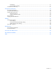
Illustrated parts catalog Server components Item Description Spare part number Customer self repair (on page 5) Mechanical components 1 Processor air baffle 747025-001 Mandatory1 2 Drive blank 670033-001 Mandatory1 3 FBWC capacitor pack holder 669291-001 Mandatory1 System components 4 Processor — — a) 2.
Item Description Spare part number b) 3.10 GHz Intel Xeon E3-1220 v3, 80W* ** 725282-001 Optional2 c) 3.40 GHz Intel Xeon E3-1231 v3, 80W* ** 773054-001 Optional2 d) 3.50 GHz Intel Xeon E3-1241 v3, 80W* ** 773055-001 Optional2 e) 3.50 GHz Intel Xeon E3-1270 v3, 80W* ** 725285-001 Optional2 f) 3.60 GHz Intel Xeon E3-1271 v3, 80W* ** 773056-001 Optional2 g) 3.60 GHz Intel Xeon E3-1280 v3, 82W* ** 725286-001 Optional2 h) 3.
Item 13 14 15 Description Spare part number j) 800-GB, SATA ME SSD, 6G* 692167-001 Mandatory1 k) 600-GB, SATA ME SSD, 6G* 739959-001 Mandatory1 l) 400-GB, SATA ME SSD, 6G* 692166-001 Mandatory1 m) 300-GB, SATA ME SSD, 6G* 739954-001 Mandatory1 n) 200-GB, SATA ME SSD, 6G* 692165-001 Mandatory1 o) 100-GB, SATA ME SSD, 6G* 692164-001 Mandatory1 Controllers* — a) HP H220 Host Bus Adapter 660088-001 Mandatory1 b) HP Smart Array P430 Controller 729635-001 Mandatory1 FBWC options* — a) Ca
Optional: Opzionali—Parti la cui riparazione da parte del cliente è facoltativa. Si tratta comunque di componenti progettati per questo scopo. Se tuttavia il cliente ne richiede la sostituzione ad HP, potrebbe dover sostenere spese addizionali a seconda del tipo di garanzia previsto per il prodotto. 3 No: Non CSR—Alcuni componenti HP non sono progettati per la riparazione da parte del cliente. Per rispettare la garanzia, HP richiede che queste parti siano sostituite da un centro di assistenza autorizzato.
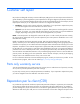
I/O module components Illustrated parts catalog 19
Item Description Spare part number 1 HP Apollo 6000 2 Slot FlexibleLOM Riser 774720-001 Mandatory1 2 I/O module adapter options — a) HP Ethernet 1-GB 4-port 366FLR Adapter 669280-001 Mandatory1 b) HP Ethernet 1-GB 4-port 331FLR Adapter* 634025-001 Mandatory1 c) HP Ethernet 10-GB 2-port 560FLR Adapter* 669281-001 Mandatory1 d) HP Ethernet 10-GB 2-port 530FLR Adapter* 649869-001 Mandatory1 e) HP Flex Fabric 10-GB 2-port 554FLR Adapter* 634026-001 Mandatory1 f) HP Flex Fabric 10-GB 2-port 52
Optional: Optional—Teile, für die das Customer Self Repair-Verfahren optional ist. Diese Teile sind auch für Customer Self Repair ausgelegt. Wenn Sie jedoch den Austausch dieser Teile von HP vornehmen lassen möchten, können bei diesem Service je nach den für Ihr Produkt vorgesehenen Garantiebedingungen zusätzliche Kosten anfallen. 3 No: Kein—Einige Teile sind nicht für Customer Self Repair ausgelegt. Um den Garantieanspruch des Kunden zu erfüllen, muss das Teil von einem HP Servicepartner ersetzt werden.
Illustrated parts catalog 22
Removal and replacement procedures Required tools You need the following items for some procedures: • T-10 Torx screwdriver • T-15 Torx screwdriver • No. 1 Phillips screwdriver • HP Insight Diagnostics (on page 50) Safety considerations Before performing service procedures, review all the safety information. Preventing electrostatic discharge To prevent damaging the system, be aware of the precautions you need to follow when setting up the system or handling parts.
This symbol on an RJ-45 receptacle indicates a network interface connection. WARNING: To reduce the risk of electric shock, fire, or damage to the equipment, do not plug telephone or telecommunications connectors into this receptacle. This symbol indicates the presence of a hot surface or hot component. If this surface is contacted, the potential for injury exists. WARNING: To reduce the risk of injury from a hot component, allow the surface to cool before touching. 6.80 kg 15.
• Remove the I/O module (on page 25). • Install the server (on page 26). Power down the server Before powering down the server for any upgrade or maintenance procedures, perform a backup of critical server data and programs. IMPORTANT: When the server is in standby mode, auxiliary power is still being provided to the system. To power down the server, use one of the following methods: • Press and release the Power On/Standby button.
2. Remove the I/O module. Install the server CAUTION: To prevent improper cooling and thermal damage, do not operate the chassis unless all bays are populated with a component or a blank. To install the component: 1. Prepare the server for installation.
2. Install the server. When seated properly, the server will be flush with the front of the chassis and the release lever will close completely without resistance. Drive blank Remove the component as indicated. CAUTION: To prevent improper cooling and thermal damage, do not operate the server unless all bays are populated with either a component or a blank. To replace the blank, slide the blank into the bay until it locks into place. Drive To remove the component: 1.
3. Remove the drive. To replace the drive, slide the drive into the bay until it is fully seated, and then close the latch handle to lock the drive in the bay. Processor air baffle To remove the component: 1. Power down the server (on page 25). 2. Disconnect all peripheral cables from the server. 3. Remove the server (on page 25). 4. Place the server on a flat, level work surface.
5. Remove the processor air baffle. To replace the component, reverse the removal procedure. I/O module FlexibleLOM adapters To remove the component: 1. Power down the server (on page 25). 2. Remove the I/O module (on page 25). 3. Remove the I/O module FlexibleLOM adapter. A T-10 screwdriver is required for this procedure. To replace the component, reverse the removal procedure.
I/O module riser assembly To remove the component: 1. Power down the server (on page 25). 2. Remove the I/O module (on page 25). 3. Remove the I/O module FlexibleLOM adapter. A T-10 screwdriver is required for this procedure. 4. Remove the I/O module riser assembly. A T-15 screwdriver is required for this procedure. To replace the component, reverse the removal procedure. DIMMs To remove the component: 1. Power down the server (on page 25).
2. Disconnect all peripheral cables from the server. 3. Remove the server (on page 25). 4. Place the server on a flat, level work surface. 5. Remove the processor air baffle ("Processor air baffle" on page 28). 6. Remove the DIMM. To replace the component, reverse the removal procedure. PCI riser board assembly To remove the component: 1. Power down the server (on page 25). 2. Disconnect all peripheral cables from the server. 3. Remove the server (on page 25). 4.
6. Remove the PCI riser board assembly. A T-10 screwdriver (for horizontal screws) and a T-15 screwdriver (for vertical screws) are required for this procedure. To replace the component, reverse the removal procedure. Controller To remove the component: 1. Power down the server (on page 25). 2. Disconnect all peripheral cables from the server. 3. Remove the server (on page 25). 4. Place the server on a flat, level work surface. 5. Disconnect all cables connected to existing expansion boards. 6.
7. Remove the controller installed on the PCI riser board assembly. A T-15 screwdriver is required for this procedure. To replace the component, reverse the removal procedure. FBWC cache module CAUTION: The cache module connector does not use the industry-standard DDR3 mini-DIMMs. Do not use the controller with cache modules designed for other controller models, because the controller can malfunction and you can lose data.
7. Disconnect the capacitor pack cable from the cache module. 8. Remove the cache module from the controller. To replace the component, reverse the removal procedure. FBWC capacitor pack CAUTION: The cache module connector does not use the industry-standard DDR3 mini-DIMMs. Do not use the controller with cache modules designed for other controller models, because the controller can malfunction and you can lose data.
3. Disconnect all peripheral cables from the server. 4. Remove the server (on page 25). 5. Place the server on a flat, level work surface. 6. Disconnect the FBWC capacitor pack cable from the FBWC cache module. 7. Remove the capacitor pack from the capacitor pack holder. To replace the component, reverse the removal procedure. FBWC capacitor pack holder CAUTION: The cache module connector does not use the industry-standard DDR3 mini-DIMMs.
6. Remove the capacitor pack from the capacitor pack holder. 7. Remove the capacitor pack holder and mounting bracket from the server.
8. Remove the FBWC capacitor pack holder from the mounting bracket. To replace the component, reverse the removal procedure. Drive cage assembly To remove the component: 1. Back up all server data on the drive. 2. Power down the server (on page 25). 3. Disconnect all peripheral cables from the server. 4. Remove the server (on page 25). 5. Place the server on a flat, level work surface. 6. Remove the PCI riser board assembly ("PCI riser board assembly" on page 31). 7.
8. Disconnect the front panel LED board assembly cables. 9. Remove all drives ("Drive" on page 27). 10. Remove the drive cage assembly. To replace the component, reverse the removal procedure. Front panel LED board assembly To remove the component: 1. Back up all server data on the drive. 2. Power down the server (on page 25). 3. Disconnect all peripheral cables from the server. 4. Remove the server (on page 25). 5. Place the server on a flat, level work surface.
6. Remove the PCI riser board assembly ("PCI riser board assembly" on page 31). 7. Disconnect the front panel LED board assembly cables. 8. Remove the front panel LED board assembly. To replace the component, reverse the removal procedure. System battery If the server no longer automatically displays the correct date and time, then replace the battery that provides power to the real-time clock. Under normal use, battery life is 5 to 10 years.
WARNING: The computer contains an internal lithium manganese dioxide, a vanadium pentoxide, or an alkaline battery pack. A risk of fire and burns exists if the battery pack is not properly handled. To reduce the risk of personal injury: • • • • Do not attempt to recharge the battery. Do not expose the battery to temperatures higher than 60°C (140°F). Do not disassemble, crush, puncture, short external contacts, or dispose of in fire or water. Replace only with the spare designated for this product.
2. Disconnect all peripheral cables from the server. 3. Remove the server (on page 25). 4. Place the server on a flat, level work surface. 5. Remove the processor air baffle ("Processor air baffle" on page 28). 6. Remove the heatsink: a. Loosen one pair of diagonally opposite screws halfway, and then loosen the other pair of screws. b. Completely loosen all screws in the same sequence. c. Remove the heatsink from the processor backplate. To replace the component: 1.
CAUTION: Heatsink retaining screws should be tightened or loosened in diagonally opposite pairs (in an "X" pattern). Do not overtighten the screws as this can damage the board, connectors, or screws. Use the wrench supplied with the system to reduce the possibility of overtightening the screws. 3. Install the heatsink: a. Position the heatsink on the processor backplate. b. Tighten one pair of diagonally opposite screws halfway, and then tighten the other pair of screws. c.
3. Disconnect all peripheral cables from the server. 4. Remove the server (on page 25). 5. Place the server on a flat, level work surface. 6. Remove the processor air baffle ("Processor air baffle" on page 28). 7. Remove the heatsink: a. Loosen one pair of diagonally opposite screws halfway, and then loosen the other pair of screws. b. Completely loosen all screws in the same sequence. c. Remove the heatsink from the processor backplate.
9. Grasp the processor by the edges, and then lift it out of the socket. To install the processor: CAUTION: THE PINS ON THE SYSTEM BOARD ARE VERY FRAGILE AND EASILY DAMAGED. To avoid damage to the system board: • Do not touch the processor socket contacts. • Do not tilt or slide the processor when lowering the processor into the socket. 1. Install the processor. Use the notches on both sides of the processor to properly align it into the socket.
2. Close the processor retaining bracket, and then secure the processor locking lever. 3. Clean the old thermal grease from the heatsink with the alcohol swab. Allow the alcohol to evaporate before continuing. 4. Apply all the grease to the top of the processor in the following pattern to ensure even distribution. 5. Install the heatsink. 6. Install the processor air baffle ("Processor air baffle" on page 28).
7. Install the server into the chassis ("Install the server" on page 26). 8. Connect all peripheral cables to the server. 9. Press the Power On/Standby button. The server exits standby mode and applies full power to the system. The system power LED changes from amber to green. System board To remove the component: 1. Power down the server (on page 25). 2. Disconnect all peripheral cables from the server. 3. Remove the server (on page 25). 4. Place the server on a flat, level work surface. 5.
To replace the system board: 1. Install the system board. 2. Connect all cables disconnected from the failed system board. 3. Install all processors ("Processor" on page 42). 4. Install all heatsinks ("Heatsink" on page 40). 5. Install all DIMMs ("DIMMs" on page 30). 6. Install the processor air baffle ("Processor air baffle" on page 28). 7. Install the FBWC capacitor pack holder ("FBWC capacitor pack holder" on page 35). 8. Install the FBWC capacitor pack ("FBWC capacitor pack" on page 34).
Warning: The serial number should ONLY be modified by qualified service personnel. This value should always match the serial number located on the chassis. 5. Press the Enter key to clear the warning. 6. Enter the serial number and press the Enter key. 7. Select Product ID. The following warning appears: Warning: The Product ID should ONLY be modified by qualified service personnel. This value should always match the Product ID located on the chassis. 8. Enter the product ID and press the Enter key.
Troubleshooting Troubleshooting resources The HP ProLiant Gen8 Troubleshooting Guide, Volume I: Troubleshooting provides procedures for resolving common problems and comprehensive courses of action for fault isolation and identification, issue resolution, and software maintenance on ProLiant servers and server blades. To view the guide, select a language: • English (http://www.hp.com/support/ProLiant_TSG_v1_en) • French (http://www.hp.com/support/ProLiant_TSG_v1_fr) • Spanish (http://www.hp.
Diagnostic tools Product QuickSpecs For more information about product features, specifications, options, configurations, and compatibility, see the product QuickSpecs on the HP website (http://www.hp.com/go/qs).
HP Insight Remote Support is available as part of HP Warranty, HP Care Pack Service, or HP contractual support agreement. Integrated Management Log The IML records hundreds of events and stores them in an easy-to-view form. The IML timestamps each event with 1-minute granularity.
operating system is functioning properly, the system periodically resets the timer. However, when the operating system fails, the timer expires and restarts the server. ASR increases server availability by restarting the server within a specified time after a system hang. At the same time, the HP SIM console notifies you by sending a message to a designated pager number that ASR has restarted the system. You can disable ASR from the System Management Homepage or through RBSU.
Component identification Front panel components Item Description 1 Drive bay 2 (node 1) 2 Drive bay 1 (node 1) 3 SUV connector (node 1) 4 SUV connector (node 2) 5 Drive bay 2 (node 2) 6 Drive bay 1 (node 2) 7 Server release lever 8 Server release latch 9 Serial label pull tab Component identification 53
Front panel LEDs and buttons Item Description Status 1 NIC 1 LED (node 1) Solid green = Link to network Flashing green (1 Hz/cycle per sec) = Network active Off = No network activity 2 Health LED (node 1) Solid green = Normal Flashing amber = System degraded Flashing red (1 Hz/cycle per sec) = System critical Fast-flashing red (4 Hz/cycles per sec) = Power fault 3 NIC 2 LED (node 2) Solid green = Link to network Flashing green (1 Hz/cycle per sec) = Network active Off = No network activity 4 H
Item Description Status 6 Power On/Standby button and system power LED (node 2) Solid green = System on Flashing green (1 Hz/cycle per sec) = Performing power on sequence Solid amber = System in standby Off = No power present 7 UID button/LED (node 1) Solid blue = Activated Flashing blue (1 Hz/cycle per sec) = Remote management or firmware upgrade in progress Off = Deactivated 8 Power On/Standby button and system power LED (node 1) Solid green = System on Flashing green (1 Hz/cycle per sec) = Per
Item Description 16 PCIe riser board connector (node 2) 17 System maintenance switch (node 2) 18 Drive backplane power connector (node 2) DIMM slot locations DIMM slots are numbered sequentially (1 through 4) for each processor. The supported AMP modes use the alpha assignments for population order, and the slot numbers designate the DIMM slot ID for spare replacement. The arrow indicates the front of the server.
Drive numbering Item Description 1 Drive bay 2 (node 1) 2 Drive bay 1 (node 1) 3 Drive bay 1 (node 2) 4 Drive bay 2 (node 2) Hot-plug drive LED definitions Item LED Status Definition 1 Locate Solid blue The drive is being identified by a host application.
Item 2 3 4 LED Activity ring Do not remove Drive status Status Definition Flashing blue The drive carrier firmware is being updated or requires an update. Rotating green Drive activity Off No drive activity Solid white Do not remove the drive. Removing the drive causes one or more of the logical drives to fail. Off Removing the drive does not cause a logical drive to fail. Solid green The drive is a member of one or more logical drives.
Cabling Internal server cabling This section provides guidelines that help you make informed decisions about cabling the server and hardware options to optimize performance. CAUTION: When routing cables, always be sure that the cables are not in a position where they can be pinched or crimped.
Front panel LED board assembly cabling FBWC capacitor pack cabling SUV cable connectors CAUTION: Before disconnecting the SUV cable from the connector, always squeeze the release buttons on the sides of the connector. Failure to do so can result in damage to the equipment.
Item Connector Description 1 Serial For trained personnel to connect a null modem serial cable and perform advanced diagnostic procedures 2 USB For connecting up to two USB devices 3 Video For connecting a video monitor Cabling 61
Specifications Environmental specifications Specification Value Temperature range* — Operating 10°C to 35°C (50°F to 95°F) Shipping -40°C to 70°C (-40°F to 158°F) Maximum wet bulb temperature 28°C (82.4°F) 82 W CPU option 10°C to 25°C (50°F to 77°F) Relative humidity (noncondensing)** — Operating 10% to 90% Nonoperating 5% to 95% * All temperature ratings shown are for sea level. An altitude derating of 1°C per 300 m (1.8°F per 1,000 ft) to 3,048 m (10,000 ft) is applicable.
Acronyms and abbreviations ABEND abnormal end AMP Advanced Memory Protection ASR Automatic Server Recovery CSR Customer Self Repair HP SIM HP Systems Insight Manager iLO Integrated Lights-Out IML Integrated Management Log LOM LAN on Motherboard NVRAM nonvolatile memory PCI peripheral component interconnect PCIe Peripheral Component Interconnect Express POST Power-On Self Test Acronyms and abbreviations 63
RBSU ROM-Based Setup Utility SAS serial attached SCSI SD Secure Digital SFF small form factor SIM Systems Insight Manager SPP HP Service Pack for ProLiant SUV serial, USB, video TPM Trusted Platform Module UID unit identification USB universal serial bus Acronyms and abbreviations 64
Documentation feedback HP is committed to providing documentation that meets your needs. To help us improve the documentation, send any errors, suggestions, or comments to Documentation Feedback (mailto:docsfeedback@hp.com). Include the document title and part number, version number, or the URL when submitting your feedback.
Index A air baffle 15, 28 Automatic Server Recovery (ASR) 51 B backplane, hard drive 15 battery 15, 39, 55 blank, hard drive 15 blanks 15 button, UID 54 buttons 23, 53 buttons, front panel 53, 54 C cable routing diagrams 59, 60 cable, Mini-SAS 15, 37, 59 cable, SUV 15, 60 cables 15, 59 cables, overview 59 cabling 59, 60 cache module 15, 33 cache module, removing 33 capacitor pack 15, 34 capacitor pack cabling 60 capacitor pack holder 15, 35 cautions 24 components 15, 19, 53 components, identification 15,
H M hard drive blanks 27 HBA options 15, 32 health LED 54 heatsink 15, 40 hot-plug drive 27 hot-plug drive, removing 27 HP Insight Diagnostics 50 HP Insight Diagnostics survey functionality 50 HP Insight Remote Support software 50 HP Management Packs 1.1 for MOM 2005, troubleshooting 49 HP Management Packs 1.
server release latch 53 server release lever 53 server specifications 62 server, removal 25 SFF drive cage 15 SFF drives 15 Smart Array options 15, 32 spare part numbers 15, 19 specifications 62 specifications, environmental 62 specifications, server 62 SSD options 15 static electricity 23 SUV cable 15, 60 SUV connector 53, 60 symbols on equipment 23 system battery 15, 39, 55 system board 15, 46, 55 system components 53, 55 system maintenance switch 55, 56 system power LED 54 T technical support 5 temperat