
HP PS1810-24G Quick Setup Guide and Safety/Regulatory Information (5998-4024)

1
HP PS1810-24G Switch Quick Setup Guide,
and Safety/Regulatory Information
For more detailed instructions and information to set up your switch, view or download the Installation and Getting Started
Guide for your switch at www.hp.com/networking/support.
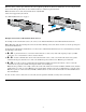
1. Unpack and check included parts. ■ Documentation kit
■ Switch
■ Accessory kit (installation hardware)
■ AC power cord
2. Prepare for installation. To avoid personal injury or product damage, follow the “Installation Precautions”
on page 6.
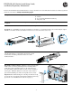
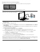
3. Mount the switch. Mount it in a rack, on a wall, or on top of or under a horizontal surface.
In a Rack: Use a #1 Phillips (cross-head) screwdriver to attach the accessory kit brackets to the switch using the eight 8-
mm M4 screws. Then use the four number 12-24 screws to secure the brackets to the rack.
On a Horizontal Surface: Attach the four self-adhesive
pads (included in the accessory kit) to the bottom corners
of the switch, and then position the switch on a stable
horizontal surface.
On a Wall or Under a Surface: Install two 5/8-inch (15.875 mm)
number 12 wood screws, (included) into the mounting surface,
positioned 10 inches (254 mm) apart. Use the wall anchors if
necessary. Then, position the switch over the screws and slide to
lock in place. Install the third screw at the side of the switch to
prevent it from sliding out of the locked position, if necessary.
Important: For wall-mounting, the network ports must be facing
up or down. Do not mount the switch with ventilation holes facing
up or down. (See “Installation Precautions” on page 6.)
1
1
2
2
1
2
3
1
2
5/8-inch #12
screws