HP PS1810 Switches Management and Configuration Guide
HP PS1810 Switches June 2013 Management and Configuration Guide i
© Copyright 2013 Hewlett-Packard Development Company, L.P. The information contained herein is subject to change without notice. All Rights Reserved. Disclaimer This document contains proprietary information, which is protected by copyright. No part of this document may be photocopied, reproduced, or translated into another language without the prior written consent of Hewlett-Packard.
Preface Preface About This Document The HP PS1810 series switches are purpose built layer 2 web-managed switches, specially designed to work with HP ProLiant Gen8 servers. The HP PS1810 series switches provide reliable, plug-and-play Gigabit network connectivity, consolidated management features, network security capabilities, enhancements to ease of use, improved energy efficiency, and expanded deployment flexibility. The HP PS1810 series switches are ideal for deployment with HP ProLiant Gen8 servers.
Preface Note For the latest version of all HP documentation, visit the HP Web site at www.hp.com/networking/support. Then select your switch product.
Contents Preface About This Document . . . . . . . . . . . . . . . . . . . . . . . . . . . . . . . . . . . . . . . . . . . . . . . . . . . . . . . . . . . . . . . . . . iii About Your Switch Manual Set . . . . . . . . . . . . . . . . . . . . . . . . . . . . . . . . . . . . . . . . . . . . . . . . . . . . . . . . . . iii Supported Features . . . . . . . . . . . . . . . . . . . . . . . . . . . . . . . . . . . . . . . . . . . . . . . . . . . . . . . . . . . . . . . . . . . .
4 Switching Port Configuration . . . . . . . . . . . . . . . . . . . . . . . . . . . . . . . . . . . . . . . . . . . . . . . . . . . . . . . . . . . . . . . . . . . 4-1 Auto Detect and Configure Fiber Modules . . . . . . . . . . . . . . . . . . . . . . . . . . . . . . . . . . . . . . . . . . . 4-1 Jumbo Frames . . . . . . . . . . . . . . . . . . . . . . . . . . . . . . . . . . . . . . . . . . . . . . . . . . . . . . . . . . . . . . . . . . . . . . 4-2 Port Mirroring . . . . . . . . . . . . . . . . . . . . .
10 Maintenance Backup Manager . . . . . . . . . . . . . . . . . . . . . . . . . . . . . . . . . . . . . . . . . . . . . . . . . . . . . . . . . . . . . . . . . . . 10-1 Example—Backing Up a Configuration File . . . . . . . . . . . . . . . . . . . . . . . . . . . . . . . . . . . . . . . . 10-2 Update Manager . . . . . . . . . . . . . . . . . . . . . . . . . . . . . . . . . . . . . . . . . . . . . . . . . . . . . . . . . . . . . . . . . . . . 10-4 Example—Updating the Switch Software . . . . . . . . . . . . .
viii
Getting Started Connecting the Switch to a Network 1 Getting Started This chapter describes how to make the initial connections to the switch and provides an overview of the Web interface. Connecting the Switch to a Network To enable remote management of the switch through a Web browser, the switch must be connected to the network. By default, the switch is configured with DHCP enabled. The switch must be connected to the same network as the DHCP server.
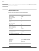
Getting Started Connecting the Switch to a Network Operating System and Browser Support The following operating systems and browsers with JavaScript enabled are supported: 1-2 Operating System Browser Windows XP SP3 Firefox 6, 7, 19, 20 Internet Explorer 7, 8 Google Chrome 13, 14, 25 Windows 7 Firefox 6, 7, 19, 20 Internet Explorer 8, 9, 10 Google Chrome 13, 14, 25 MacOS Firefox 6, 7, 18, 19 Google Chrome 13, 14, 25
Getting Started Getting Started With the Web Interface Getting Started With the Web Interface This section describes the following Web pages: ■ “Logging On” on page 1-3 ■ “Interface Layout and Features” on page 1-3 Logging On Follow these steps to log on through Web interface: 1. Open a Web browser and enter the IP address of the switch in the Web browser address field. The default IP address is 192.168.2.10. This address is used if DHCP is unable to configure the server address.
Getting Started Getting Started With the Web Interface Figure 1-2. Interface Layout and Features Navigation Pane Web Applet Common Links Click on any topic in the navigation page to display related configuration options. The System Description page displays when you first log on and when you click Home or Status > System Description in the navigation pane. See “System Description” on page 2-1 for more information. You can click Network Setup > Get Connected to display this page.
Getting Started Getting Started With the Web Interface ■ Click Support to access the HP Networking Web site (Internet access required). ■ Click Logout to end the current management session. Saving Changes When you click memory. A progress indicator , changes are saved automatically to the system configuration file in flash is displayed next to the Help link while the operation is in progress. User-Defined Fields User-defined fields can contain 1–31 characters, including hyphens, commas, and spaces.
Getting Started Getting Started With the Web Interface • ■ ■ Off—The switch is NOT receiving power. Fault (Orange) • Blinking—A fault has occurred, other than during self-test. • On—Self-test in progress. • Off—The switch is operating properly. Locator (Blue) on PS1810-24G only • Blinking—The switch is in Locate mode, attempting to locate a specific switch. • Off—The locator is disabled. This mode can be enabled using the Web interface. See “Locator” on page 9-5.
Status System Description 2 Status You can use the Status pages to view system information and statistics. System Description The System Description page displays basic information such as the product name, model, ports, and switch type: Gigabit Ethernet or a Fast Ethernet. The software and boot ROM versions are also displayed. In addition, the system name, location, and contact can be configured on this page.
Status System Description Table 2-1. System Description Fields Note 2-2 Field Description System Description The product name of the switch including the model, ports, and whether a Gigabit Ethernet or a Fast Ethernet switch. The software and Boot ROM version are also displayed. System Name Enter the preferred name to identify this switch. A maximum of 31 alpha-numeric characters including hyphens, commas and spaces are allowed. This field is blank by default.
Status Log Log The Log status page displays logged system messages, such as configuration failures and user sessions. The log page displays the 100 most recent log entries. The newest log entry, by default, is displayed at the bottom of the list.
Status Log Field Description Log Message Log Index Log number in the log table. Severity Severity associated with the log message. Log Time Time at which the log was entered in the table. Component Component from which the massage was logged. Description Description of the entry. For information about configuring log settings, see “Log Configuration” on page 9-2.
Status Port Summary Port Summary The Port Summary page displays a summary of network traffic from the ports. This summary can be used to identify potential problems with the switch. It also helps to identify what has been configured on this port. The displayed values are accumulated after the last clear operation. Refreshing the page shows the latest statistics, which provide per-port statistics on packets transmitted and received for all the ports.
Status Port Summary Table 2-3. Port Summary Fields Field Description Port Summary Interface List of physical and logical interfaces supported or configured on a particular platform. Physical Type Displays whether the port is operating in copper mode or fiber mode. Port Status The physical status (up or down) of the link at the port. AutoNeg Status Displays whether Auto negotiation is enabled or disabled on the port. Link Speed The physical speed at which the port is operating.
Status LLDP Statistics LLDP Statistics The Link Layer Discovery Protocol (LLDP) Statistics page displays summary and per-port information for LLDP frames transmitted and received on the switch. To display the LLDP Statistics page, click Status > LLDP Statistics in the navigation pane. Figure 2-4.
Status LLDP Statistics Table 2-4. LLDP Statistics Page Fields Field Description LLDP Global Statistics Insertions The number of times the complete set of information advertised by a particular MAC Service Access Point (MSAP) has been inserted into tables associated with the remote systems. Deletions The number of times the complete set of information advertised by a particular MSAP has been deleted from tables associated with the remote systems.
Status Trunk Trunk The Trunk status page displays the configuration summary and status of each trunk. To display the Trunk page, click Status > Trunk in the navigation pane. Figure 2-5 displays the configuration summary and status of a trunk named Trunk1. This trunk is configured in dynamic mode and has 3 and 5 interfaces as its active members. Figure 2-5. Trunk Page Table 2-5. Trunk Port Configuration Fields Field Description Trunk ID assigned to the trunk by the system when the trunk is created.
Status MAC Table MAC Table The MAC Table page displays the MAC addresses configured for ports, and the MAC type including the maximum entries supported an d the current number of entries learned. The default aging interval for forwarding database is 300secs. Dynamically learned entries are removed if they are not updated within the aging interval on a particular interface To display the MAC Table page, click Status > MAC Table in the navigation pane. Figure 2-6. MAC Table Page Table 2-6.
Status Loop Protection Loop Protection The Loop Protection status page displays a summary of loop protection configuration data on the switch and on each port, and loop protection network traffic for the switch and status information for each port. To display the Loop Protection status page, click Status > Loop Protection in the navigation pane. Figure 2-7. Loop Protection Page Table 2-7. Loop Protection Fields ■ Field Description Interface List of ports with loop protection currently enabled.
Status Spanning Tree Spanning Tree The Spanning Tree status page displays the global bridge configuration and the per-port spanning tree states. To display the Spanning Tree page, click Status > Spanning Tree in the navigation pane. Figure 2-8. Spanning Tree Status Page Table 2-8. Spanning Tree Fields Field Description Spanning Tree Bridge Status 2-12 Spanning Tree The current operational state of the bridge (enabled or disabled).
Status Spanning Tree Field Description Root Path Cost The sum of the Port Path costs on the least cost path to the Root bridge. For the Root bridge this is zero. Root Port The port on the switch that forwards traffic toward the Spanning Tree root. Topology Change Count Number of topology changes since STP was enabled. Time Since Last Change Time since last topology change was detected. Spanning Tree Interface Status Root Guarded Interfaces Interfaces with the Root Guard parameter currently set.
Status Green Features Green Features The Green Features status page displays the status of the power-saving or green features. To display the Green Features page, click Status > Green Features in the navigation bar. Figure 2-9.
Status Green Features Table 2-9. Green Features Status Fields Field Description Port Energy Saving Configuration Auto Port Power-Down The current Auto Port Power-Down setting (Enabled or Disabled). When enabled, the port is set in power save mode when there is no link. Low-Traffic Idle (EEE) The current Energy Efficient Ethernet (EEE) setting (Enabled or Disabled).
Status Dual Image Dual Image The Dual Image status page displays the status of the two software images (image1 and image2) on the switch. It also provides details about the current active and alternate images, and software image versions. To display the Dual Image page, click Status > Dual Image in the navigation bar. As shown in Figure 2-10, Image1 is the active image and will continue to be the active image after a reboot. Figure 2-10. Dual Image Status Page Table 2-10.
Status Clock Clock The Clock status page displays the current time, time zone, and Daylight Savings Time settings. To display the Clock page, click Status > Clock in the navigation bar. Figure 2-11. Clock Status Page Table 2-11. Clock Status Fields Field Description Current Time Time The current time. This value is determined by an SNTP server. When SNTP is disabled, the system time increments from 00:00:00, 1 Jan 1970, which is set at bootup. Date The current date.
Status Clock 2-18
Network Setup Get Connected 3 Network Setup You can use the Network Setup pages to configure how a management computer connects to the switch and how the switch connects to a server to synchronize its time. Get Connected Use the Get Connected page to configure settings for the network interface. The network interface is defined by an IP address, subnet mask, and gateway address. Any one of the switch's front-panel ports can be selected as the management port for the network interface.
Network Setup Get Connected Table 3-1. Get Connected Fields Field Description Network Details Protocol Type Select the type of network connection: • Static: Select this option to enable the IP address, mask, and gateway fields for data entry. • DHCP: This default option enables the switch to obtain IP information from a DHCP server on the network. If the DHCP server responds, then that IP address is used.
Network Setup Get Connected Field Description Community Name Specify a community name or use the default name, public. The switch supports the following MIBs: • BRIDGE-MIB (IEEE 802.1Q) • LLDP-MIB (IEEE 802.3AB) • EtherLike-MIB • IF-MIB • RFC1213-MIB • RMON-MIB (RMON History as in v1) Click Apply to save any changes for the current boot session; the changes take effect immediately. Note A power cycle does not reset the IP address to its factory-default value.
Network Setup Simple Network Time Protocol Simple Network Time Protocol The HP PS1810 series switch software supports the Simple Network Time Protocol (SNTP). SNTP ensures accurate network device clock time synchronization up to the millisecond. Time synchronization is performed by a network SNTP server. The software operates only as an SNTP client and cannot provide time services to other systems. The SNTP server port of 123 is used by default.
Network Setup Simple Network Time Protocol Table 3-2. SNTP Fields Field Description Enable SNTP Select to enable SNTP client mode. Clear to disable SNTP client mode. When disabled, the system time increments from 00:00:00, 1 Jan 1970, which is set at bootup. SNTP/NTP Server Specify the IP address of the SNTP server to send requests to. Server Port Specify the server's UDP port to listen for responses/broadcasts (range 1–65535, default = 123).
Network Setup Time Zone Time Zone The Time Zone page is used to configure your local time zone. The switch must be configured to acquire the time from an SNTP server. An acronym can also be assigned to a selected time zone. No time zone is configured by default. To display the Time Zone page, click Network Setup > Time Zone in the navigation pane. Figure 3-3. Time Zone Page Table 3-3. Time Zone Fields Field Description Time Zone Select the time zone for your location.
Network Setup Daylight Saving Time Daylight Saving Time The Daylight Saving Time page is used to configure if and when Daylight Saving Time (DST) occurs for your time zone. When configured, the system time will adjust automatically during Daylight Saving Time. To display the Daylight Saving Time page, click Network Setup > Daylight Saving Time in the navigation pane. The page displays differently depending on the mode selected in the Daylight Saving Time field.
Network Setup Daylight Saving Time Table 3-4. Daylight Saving Time Fields Field Description Daylight Saving Time Select how DST will operate: • Disabled— No clock adjustment will be made for DST. • Recurring— The settings will be in effect for the upcoming period and subsequent years. • Non-Recurring— The settings will be in effect for only one period (i.e., they will not carry forward to subsequent years).
Switching Port Configuration 4 Switching You can use the Switching Pages to configure port operation and capabilities. Port Configuration Use the Port Configuration page to view and configure the Admin mode and link speed setting for each port on the switch. It is also used to display the link status and physical type of each switch port.
Switching Jumbo Frames Table 4-1. Port Configuration Fields Field Description Interface Select the interface to configure. Physical Type Describes the port type (i.e., Copper or Fiber). Link Status Displays Up or Down to indicate operational status. Admin Mode Enable access to the port on the network. Clear to disable the port. Link Speed Configure the duplex mode and transmission rate for the selected port. (These options may change depending on the port type.
Switching Port Mirroring Port Mirroring Port mirroring sends a copy of all packets sent and/or received on one port (the source port) to another port (the destination port) for monitoring and analysis by an external network analyzer. Multiple switch ports can be configured as source ports, with each port mirrored to the same destination. You can also mirror the internal CPU traffic to an external port for debugging the CPU. No destination port is defined by default.
Switching Port Mirroring Table 4-3. Port Mirroring Fields Field Description Enable Mirroring Enable port mirroring capability globally on the switch. Clear to disable the feature. Destination Port Select the port to which packets will be mirrored. Source Port Direction For each source port you want to mirror to the destination port, select the direction of the packets to be mirrored: • Tx and Rx— All packets transmitted and received on the source port are mirrored.
Switching Flow Control Flow Control When a port becomes oversubscribed, it may begin to lose data by dropping traffic intermittently. When 802.3x flow control is enabled, a lower-speed switch is able to communicate with a higher-speed switch without losing data by requesting that the higher-speed switch refrain from sending packets. Transmissions are temporarily halted to prevent buffer overflows. Note Flow control works well when the Link Speed is auto-negotiated.
Switching Green Features Green Features The switch software allows the user to enable or disable port, cable, and LED energy saving features that consume less power than the normal high-performance mode. To display the Green Features configuration page, click Switching > Green Features in the navigation pane. Figure 4-5.
Switching Green Features Table 4-5. Green Features Configuration Fields Field Description Port Energy Saving Configuration Auto Port PowerDown Enable power save mode when there is no link. This feature is disabled by default. Low-Traffic Idle (EEE) EEE (Energy Efficient Ethernet) is designed to save power by turning off network ports that are not passing traffic. EEE works for ports in auto-negotiation mode, where the port is negotiated to either 100 Mbps Full Duplex or 1 Gbps (1000 Mbps) Full Duplex.
Switching Loop Protection Loop Protection Loops in a network can consume switch resources and degrade performance. Detecting loops manually can be very cumbersome and time consuming. The HP PS1810 series switch software provides an automatic Loop Protection feature. Loop Protection may be enabled or disabled globally and on a port-by-port basis.
Switching Loop Protection Table 4-6. Loop Protection Fields Field Description Loop Protection Enable this feature globally. Transmission Time Enter the time interval, in seconds, between sending Loop Protection packets. Shutdown Time Set the number of seconds that a port remains shut down if a loop has been detected on the port. Loop Protection Select Select how you want to configure Loop Protection: • All— Enables all interfaces with Loop Protection.
Switching Spanning Tree Spanning Tree The Rapid Spanning Tree Protocol (RSTP, IEEE 802.1w) reduces the convergence time for network topology changes to about 3-5 seconds from the 30 seconds or more for the IEEE 802.1D STP standard. RSTP is intended as a complete replacement for STP, but can still interoperate with switches running the STP protocol by automatically reconfiguring ports to STP-compliant mode if they detect STP protocol messages from attached devices.
Switching Spanning Tree Field Description Max Age Specify the number of seconds from 6 seconds and 40 seconds until the BPDU information is considered to be aged out or invalid. This value must be <= (FwdDelay-1)*2 and >= (HelloTime+1)*2. The default is 20 seconds. Spanning Tree Interface Configuration BPDU Port Error Recovery Set the port to recover from an error-disabled state. If recovery is not enabled, a port has to be disabled and re-enabled for normal STP operation.
Switching Spanning Tree 4-12
Security Advanced Security 5 Security The HP PS1810 series switch software includes a robust set of built-in denial-of-service (DoS) and storm-control protections, and allows configuring secure HTTP (HTTPS) management sessions. Advanced Security The HP PS1810 series switch software provides the following built-in security features: C a u ti o n ■ Storm Control—This feature protects against condition where incoming packets flood the LAN, causing network performance degradation.
Security Secure Connection Table 5-1. Advanced Security Fields Field Description Storm Control Activate storm control protection for broadcast and multicast globally in the system. The default threshold is 64K pps. Clear to not use the Storm Control feature. Auto DoS Enable denial of service attack protection, or clear to disable DoS protection. It is disabled by default. Click Apply to save any changes for the current boot session; the changes take effect immediately.
Security Secure Connection You can also download the encryption parameter files that provide algorithms for encrypting the key exchanges. To manage HTTP parameters and certificates, you use both the Secure Connection page and the Update Manager page. To display the Secure Connection page, click Security > Secure Connection in the navigation pane. Figure 5-2. Secure Connection Page Table 5-2. Secure Connection Fields Note Field Description HTTP Admin Mode Enable the Administrative mode of HTTP.
Security Secure Connection Downloading SSL Certificates and Diffie-Hellman Files Use the Update Manager page to download a public key certificate that has been signed by another server, or a root certificate that has been signed by a certificate authority. You can also download DiffieHellman (DH) encryption parameter files, which establish the algorithms for encrypting key exchanges.
Security Secure Connection Generating Certificates To have the switch generate the certificates: 1. Click Generate Certificates. The page refreshes with the message “Certificate has been generated.” 2. Click Apply to complete the process. When the process is complete, the page refreshes with the message “No certificate generation in progress,” and the Certificate Present field displays as True. When a certificate is present a Delete button appears to enable deleting the certificate.
Security Secure Connection 5-6
Trunks Trunk Configuration and Membership 6 Trunks Trunks allow for the aggregation of multiple full-duplex Ethernet links into a single logical link. Network devices treat the aggregation as if it were a single link, which increases fault tolerance and provides load sharing capability. You assign the trunk VLAN membership after a trunk is created. A trunk interface can be either static or dynamic, but not both. ■ Dynamic trunks use the Link Aggregation Control Protocol (LACP, IEEE standard 802.3ad).
Trunks Trunk Configuration and Membership Figure 6-1. Trunk Configuration Page Table 6-1. Trunk Configuration Fields Field Description Trunk Trunk ID for the settings. “Normal” indicates the port is not part of any trunk. Name Trunk name. A trunk name can have any case-sensitive combination of up to 15 alpha-numeric characters and can contain ‘-’, ‘_’, and ‘.’ (a-z, A-Z, 0-9,-,_, and .). Mode Mode configured for the trunk. Port Members Select the trunk membership for a port.
Trunks Trunk Configuration and Membership ■ LACP Passive—Trunk will only participate if the other end sends LACPDUs (other end is active). Click Apply to save any changes to the currently selected trunk. The changes take effect immediately. Example—Creating a Trunk Follow these instructions to set up a trunk and manually add port members using the Static mode. 1. Click Trunk > Trunk Configuration in the navigation pane to display the Trunk Configuration page. Figure 6-2. Trunk Configuration Page 2.
Trunks Trunk Configuration and Membership Figure 6-4. Trunk Mode 4. Select ports to add them to the trunk. Figure 6-5. Trunk Ports 5. 6-4 Click Apply to set up a trunk with the selected port members.
Virtual LAN VLAN Configuration 7 Virtual LAN On a Layer 2 switch, Virtual LAN (VLAN) support offers some of the benefits of both bridging and routing. Like a bridge, a VLAN switch forwards traffic based on the Layer 2 header, which is fast, and like a router, it partitions the network into logical segments, which provides better administration, security and management of multicast traffic. A VLAN is a set of end stations and the switch ports that connect them.
Virtual LAN VLAN Ports Table 7-1. VLAN Configuration Fields Field Description Create VLAN Select this box to create a new VLAN. Create VLAN ID Specify the numeric VLAN Identifier from 2 to 4094 and click Apply to create the VLAN. Note: VLAN ID 1 is pre-configured on the switch and is always named “Default.” The default VLAN cannot be deleted. Number of VLANs The current number of VLANs. Up to 64 VLANs can be created.
Virtual LAN VLAN Participation / Tagging Note Ingress Filtering is enabled on all ports. A frame is discarded if the port is not a member of the VLAN that the frame is associated with. In a tagged frame, the VLAN is identified by the VLAN ID in the tag. In an untagged frame, the VLAN is the Port VLAN ID specified for the port that received the frame. Click Apply to save any changes for the current boot session; the changes take effect immediately.
Virtual LAN Advanced Configuration Table 7-3. Participation/Tagging Fields Field Description VLAN Select the VLAN to configure. Tag / Untag / Exclude All For a port or trunk to participate in a VLAN, its tagging policy must be defined. By default, all ports and trunks are configured as untagged members of VLAN1, and are excluded from all other newly created VLANs. You can configure each port individually or use the Tag / Untag / Exclude All box to configure all ports at once.
Virtual LAN Advanced Configuration Figure 7-4. Advanced Configuration Page Table 7-4. Advanced Configuration Fields Field Description Management VLAN ID ID of the management VLAN IP Address IP address of the management VLAN Subnet Mask Subnet mask of the management VLAN VLAN ID Select a VLAN ID.
Virtual LAN Advanced Configuration 7-6
Link Layer Discovery Protocol (LLDP) LLDP Configuration 8 Link Layer Discovery Protocol (LLDP) The IEEE 802.1AB defined standard, Link Layer Discovery Protocol (LLDP), allows stations residing on an IEEE 802 LAN to advertise major capabilities and physical descriptions. This information is viewed by a network manager to identify system topology and detect bad configurations on the LAN. LLDP is a one-way protocol; there are no request/response sequences.
Link Layer Discovery Protocol (LLDP) LLDP Configuration Table 8-1. LLDP Configuration Fields Field Description Global Mode Transmit Interval Specify the interval at which frames are transmitted. The default is 30 seconds, and the valid range is 5–32768 seconds. Transmit Hold Specify the multiplier on the transmit interval to, which is used to compute the TTL (range 2–10, default = 4). Re-Initialization Delay Specify the delay before a re-initialization (range 1–10 seconds, default = 2).
Link Layer Discovery Protocol (LLDP) LLDP Local Device LLDP Local Device Use the LLDP Local Device page to view information about devices on the network for which the switch has received LLDP information. To display the Local Device page, click LLDP > Local Device in the navigation pane. Figure 8-2. LLDP Local Device Page Table 8-2. LLDP Local Device Fields Field Description Local Device Summary Chassis ID The source of the chassis identifier (System MAC address).
Link Layer Discovery Protocol (LLDP) LLDP Remote Device LLDP Remote Device Use the LLDP Remote Device page to view information about remote devices for which the switch has received LLDP information. Click the IP address link in the System IP column to navigate to a remotely connected switch. To display the Remote Device page, click LLDP > Remote Device in the navigation pane. Figure 8-3. LLDP Remote Device Page Table 8-3.
Link Layer Discovery Protocol (LLDP) Energy Efficient Ethernet Energy Efficient Ethernet EEE (Energy Efficient Ethernet) is designed to save power by turning off network ports that are not passing traffic. EEE includes a mechanism to awaken the port when it needs to send or receive traffic. The transmitter sends LPI (low power idle) signals instead of the normal idle signals to indicate that the EEE protocol is in effect.
Link Layer Discovery Protocol (LLDP) Energy Efficient Ethernet 8-6
Diagnostics Ping Test 9 Diagnostics You can use the Diagnostics features to test, configure, and reboot the HP PS1810 series switch. Ping Test Use the Ping Test page to determine whether another device on the network is reachable. Ping provides a synchronous response when initiated. To display the Ping Test page, click Diagnostics > Ping Test in the navigation pane. Figure 9-1. Ping Test Page Table 9-1.
Diagnostics Log Configuration • Transmitted Packets—The number of packets sent. • Received Packets—Number of packets received. • Min/Max/Avg RTT—Specifies the Minimum, Maximum, Average Round Trip Time (msec). Log Configuration The HP PS1810 series switch software supports logging system messages to the Log file or forwarding messages over the network using the Syslog protocol. Syslog messages can be captured by a designated host on the network that is running a Syslog daemon.
Diagnostics Reboot Switch Click Apply to save any changes for the current boot session; the changes take effect immediately. Reboot Switch Use this feature to perform a software reboot of the switch. If you applied configuration changes, wait at least one minute before rebooting to ensure that the changes are saved to the system configuration file. To display the Reboot Switch page, click Diagnostics > Reboot Switch. Figure 9-3. Reboot Switch Page Click Reboot Switch to reboot the switch.
Diagnostics Support File Support File Use the support file page to display summary information for the switch on a single page. To display the Support File page, click Diagnostics > Support File in the navigation pane. Figure 9-5.
Diagnostics Locator ■ Advanced security configuration ■ Flow control mode configuration ■ Secure connection configuration ■ MAC table ■ VLAN configuration, membership, and advanced configuration ■ Trunk configuration ■ LLDP configuration, global statistics, and interface statistics ■ LLDP local and remote device summary ■ Port mirroring configuration ■ Loop protection configuration and status ■ Spanning tree bridge configuration and status ■ Green features configuration To save the S
Diagnostics Locator 9-6
Maintenance Backup Manager 10 Maintenance Backup Manager The Backup Manager page provides a means to save a backup copy of the switch’s image or configuration files on a local system or network directory. The page displays different options depending on the protocol and image or file type selected for the backup. As shown in the example in Figure 10-1, TFTP (Trivial File Transfer Protocol) has been selected as the backup method for saving the code (entire image) onto a server.
Maintenance Backup Manager ■ Note For backup using TFTP, ensure that the TFTP server is running and click Upload. Use a TFTP application to initiate the backup. If using Internet Explorer, when you attempt a backup operation from a secure HTTP session using the HTTP protocol, you may receive the following error message, even though the document is available and downloaded from the server: Internet Explorer cannot download filename from .
Maintenance Backup Manager Figure 10-3. Backup Transfer Status C a u ti o n Do not disturb the browser window while the transfer is in progress. When the backup is complete, a confirmation is displayed. Figure 10-4. Backup Confirmation 6. Click OK. The Backup Manager page displays the transfer status message. Figure 10-5. Backup Transfer Status 7. Note Click Back to re-display the Backup Manager page. To restore a backed-up code or configuration file, use Update Manager.
Maintenance Update Manager Update Manager The Update Manager page enables a new image or configuration file to be uploaded from the local system or network to the switch. Update Manager displays different options depending on the transfer protocol, file or image type selected for an update. In the example in Figure 10-6, the inactive (or “Backup”) image on the switch is being updated from a TFTP server.
Maintenance Update Manager Field Description Image (for Code updates only) If Code is selected as the update type, select which of the two images stored on the switch is to be updated: • Active —The uploaded image will replace the currently active image. • Backup —The uploaded image will replace the backup image. Example—Updating the Switch Software C a u ti o n It is recommended that you back up the image file before updating it. See “Backup Manager” on page 101 for instructions.
Maintenance Update Manager Figure 10-8. Update Steps 7. Click OK. A progress bar indicate transfer progress. Figure 10-9. Backup Transfer Status C a u ti o n Do not disturb the browser window while the transfer is in progress. A message is displayed to confirm that the switch will be rebooted immediately to use the new configuration. Figure 10-10. Reboot Confirmation When the update is complete, a confirmation is displayed.
Maintenance Update Manager Figure 10-11. Update Confirmation 8. Click OK. Update Manager displays a transfer status message. Figure 10-12. Update Transfer Status 9. Click Back to re-display the Update Manager page. Note that, in this example, the image was downloaded as the inactive (backup) image. To complete the update process and to activate the backup image as the operating software, use the Dual Image Configuration page.
Maintenance Password Manager Figure 10-13. Dual Image Configuration Page 10. (Optional) Add a description for the selected image (Image2) and click Apply. 11. Click Activate to activate the selected image on the next reboot. Note: You can verify the next active image by viewing the Status > Dual Image screen. 12. Click Diagnostics > Reboot Switch, and then click Reboot Switch to complete the update. Figure 10-14. Reboot Switch Page Wait for the switch to reboot and display the login page. Figure 10-15.
Maintenance Dual Image Configuration Figure 10-16. Password Manager Page Note There is no default password. Passwords must be at least 8 characters but no more than 64 alphanumeric and special characters (~,`,!,@,#,$,%,^,&,*,(,),-,_,+,=,{,[,},],|,\,<,,,>,.,?,/,”,’, and space) in length, and are case sensitive. The password needs to be entered again to confirm new password. In case of a forgotten password, manually reset the switch to its factory defaults.
Maintenance Dual Image Configuration ■ Click Activate to activate the selected image selected in the Image Name field. Be sure to configure the Image Description field to the version of the image loaded so that users can easily distinguish between the images. ■ Click Apply to apply a description to the image selected in the Image Name field. ■ Click Delete to delete the image selected in the Image Name field.
Servers Monitor Servers 11 Servers Integrated Lights Out (iLO) implements secure remote management capabilities, regardless of server status or location. iLO provides periodic alerts, server status, power information, power management, and remote control capabilities that can be used to diagnose OS or server problems remotely. You can use the Monitor Servers page to monitor and add iLO enabled servers, which send periodic status updates to the HP PS1810 series switch.
Servers Monitor Servers Table 11-1. Monitored Server Fields Field Description Monitored Servers Server: System Health System health indicator for monitored server. OK— System is fully operational. Degraded— System is operating at a reduced capacity. Failed— One or more components are not operational. Not Available— System status cannot be ascertained. Server Product Name Monitored server name. A maximum of ten servers can be monitored. Server: iLO IP Address IP address of the monitored server.
Servers Monitor Servers Table 11-2. Discovered Servers Fields Field Description Discovered Servers Server Product Name Discovered server name. Server: iLO IP Address IP address of the discovered server. Add Select to add server. Click Apply to add the marked server. Click Apply under the Discovered Servers List to add a discovered server.
Servers Monitor Servers Figure 11-4. Monitor Servers Page 2. Use the Add Server drop-down list to select the Manually option for adding a server. Figure 11-5. Server Add Method 3. Enter the IP address of the server to be added in the Server IP Address field. Figure 11-6.
Servers Monitor Servers 4. Click Apply to add the server manually to the Monitored Servers list. Figure 11-7.
Servers Monitor Servers 11-6
Technology for better business outcomes To learn more, visit www.hp.com/networking/ © Copyright 2013 Hewlett-Packard Development Company, L.P. The information contained herein is subject to change without notice. The only warranties for HP products and services are set forth in the express warranty statements accompanying such products and services. Nothing herein should be construed as constituting an additional warranty.