HP R1500 G3 UPS User Guide Abstract This document includes installation, configuration, and operation information for the HP R1500 G3 UPS. This document is for the person who installs and maintains power products. HP assumes you are qualified in the servicing of high-voltage equipment and trained in recognizing hazards in products with hazardous energy levels.
© Copyright 2011, 2012 Hewlett-Packard Development Company, L.P. The information contained herein is subject to change without notice. The only warranties for HP products and services are set forth in the express warranty statements accompanying such products and services. Nothing herein should be construed as constituting an additional warranty. HP shall not be liable for technical or editorial errors or omissions contained herein. Microsoft®, Windows®, Windows Server®, and Windows Vista® are U.S.
Contents Component identification ............................................................................................................... 6 UPS UPS UPS UPS UPS UPS R1500 G3 overview ........................................................................................................................... 6 front panel ......................................................................................................................................... 6 front panel controls ......................
Power management .................................................................................................................... 29 Power Protector software .......................................................................................................................... 29 Troubleshooting .......................................................................................................................... 31 LED and audible alarm troubleshooting ...........................................
Korean notice ......................................................................................................................................... 45 Battery replacement notice........................................................................................................................ 46 Power cord statement for Japan................................................................................................................. 46 Electrostatic discharge ...................................
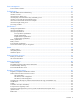
Component identification UPS R1500 G3 overview The HP UPS R1500 G3 features a 1U rack-mount design and offers power protection for loads up to 1440 VA/1000 W (NA), 1200 VA/900 W (JPN/TWN) or 1500 VA/1000 W (INTL). To benefit from the latest product enhancements, update to the latest versions of UPS firmware and software. NOTE: To download the latest versions of UPS firmware and software, see the HP website (http://www.hp.com/go/rackandpower).
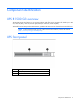
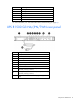
UPS front panel controls Item Description Function 1 Power On/Standby button Powers up the UPS ("Powering up the UPS" on page 17). Powers down the UPS ("Powering down the UPS" on page 21). 2 Test/Alarm Reset button Initiates a self-test ("Initiating a self-test" on page 20). Silences UPS alarms ("Silencing an audible alarm" on page 20).
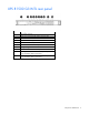
Item LED description 1 Load Segment 2 2 Load Segment 1 3 General Alarm 4 On Battery 5 Overload 6 Power On For more information, see "LED and audible alarm troubleshooting (on page 31).
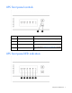
UPS R1500 G3 INTL rear panel Item Description 1 UPS option card slot 2 Input power connector (IEC-320-C14 power inlet) 3 Input circuit breaker 4 USB communications port 5 Serial communications port 6 Network Transient Protector IN jack 7 Voltage configuration DIP switches 8 Network Transient Protector OUT jack 9 Load segment 1 (two IEC-320-C13 output receptacles for surge and battery backup protection) 10 Load segment 2 (two IEC-320-C13 output receptacles for surge and battery backup p
Installation Precautions Save these instructions. This document contains important safety instructions that should be followed during installation, operation, and maintenance of the UPS and batteries. WARNING: A risk of personal injury from electric shock and hazardous energy levels exists. The installation of options and routine maintenance and service of this product must be performed by individuals who are knowledgeable about the procedures, precautions, and hazards associated with AC power products.
• Circuit overloading—Consideration should be given to the connection of the equipment to the supply circuit and the effect that overloading of the circuits might have on overcurrent protection and supply wiring. Appropriate consideration of equipment nameplate ratings should be used when addressing this concern. • Reliable earthing—Reliable earthing of rack-mounted equipment should be maintained.
2. Attach the chassis to the rack using the supplied screws. 3. (optional) Insert the rear stabilization brackets into the mounting rails and then attach the brackets to the UPS. Connecting the batteries WARNING: The unit contains sealed lead-acid battery modules. To prevent fire or chemical burns: • • • • • Do Do Do Do Do not not not not not attempt to recharge batteries after removal from the unit. disassemble, crush, or puncture the batteries. short the external contacts of the batteries.
WARNING: To prevent personal injury from hazardous energy: • Remove watches, rings, or other metal objects. • Use tools with insulated handles. • Do not place tools or metal parts on top of batteries. IMPORTANT: Before performing the following tasks, be sure that the unit is powered down and disconnected from the utility power source. NOTE: A small amount of arcing may occur when connecting the batteries. This is normal and does not damage the unit or present any safety concern.
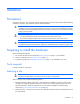
Selecting the UPS voltage configuration Using a small tool, position the DIP switches according to the desired voltage configuration. NOTE: An asterisk (*) indicates the default setting.
IMPORTANT: Power protector software requires the communications port to be appropriately cabled to the host computer. CAUTION: Only one communications port can be connected to the host computer. Connecting more than one will result in unexpected UPS behavior. If an option card is installed, the serial and USB communications ports are automatically disabled. For information about serial port pin assignment, see "Serial communications port pin assignment (on page 36)" .
2. Connect the equipment to the UPS Network Transient Protector OUT jack. Connecting the UPS to utility power WARNING: To prevent injury from electric shock or damage to the equipment: • Plug the input line cord into a grounded (earthed) electrical outlet that is installed near the equipment and is easily accessible. • Do not disable the grounding plug on the input line cord. The grounding plug is an important safety feature. • Do not use extension cords. 1.
Charging the UPS batteries Allow the batteries to charge before putting the UPS into service. IMPORTANT: Charge the batteries for at least 24 hours before supplying backup power to devices. The batteries charge to: • 90% of their capacity within 24 hours • 100% of their capacity within 48 hours Powering up the UPS Press and hold the Power On/Standby button (1) until the UPS beeps. The Power On, Load 1 and Load 2 LEDs illuminate, indicating that power is available at the UPS output receptacles.
1. Remove the two screws securing the UPS option slot cover plate, and then remove the cover plate. 2. Install the UPS Network Module along the alignment channels in the option slot. 3. Secure the UPS Network Module using the two screws removed in step 1.
4. If the UPS is powered up, you can be sure that the UPS Network Module is seated properly and communicating with the UPS by verifying that the UPS Data LED illuminates solid green, and then flashes regularly after 2 minutes. Connecting the UPS Network Module The UPS Network Module card is provided to manage the attached servers. RJ 45 network patch panel cables are required to use this card. The RJ 45 network patch panel cables are not included.
UPS operations Modes of operation The UPS has two modes of operation: • Operate mode (on page 20) • Battery mode (on page 20) Operate mode In Operate mode: • Power is available at the UPS receptacles. • The UPS charges the batteries as necessary. The UPS can be placed in Operate mode if either of the following conditions applies: • The UPS is powered up. • The UPS is powered down and no utility power is available.
IMPORTANT: • Although the audible alarm silences, the condition that caused the alarm to sound might still exist. • If a utility power failure caused the alarm (or the General Alarm LED illuminates yellow), the alarm silences after power is restored. For information about audible alarm conditions, see "LED and audible alarm troubleshooting (on page 31)." Powering down the UPS 1. Shut down all connected load devices. 2. Press the Power On/Standby button. Power to the output receptacles ceases. 3.
Maintenance Removing the UPS front bezel Replacing the batteries To replace the batteries: 1. Read and observe the requirements in "Important battery safety information (on page 22)" and "Battery care and storage guidelines (on page 23)." 2. Follow the instructions in "UPS battery replacement procedure (on page 23)." Important battery safety information WARNING: The unit contains sealed lead-acid battery modules.
NOTE: Replace all battery modules at the same time. Battery care and storage guidelines CAUTION: Because of the short shelf life of the batteries, avoid storing a battery spare as a backup. Do not maintain an inventory of spare batteries on site unless a procedure to keep these batteries charged while in storage is implemented. To maintain the batteries: • Minimize the amount of time the UPS uses battery power by matching the UPS configuration with the utility voltage.
4. Remove the battery bracket. 5. Remove the UPS battery modules. IMPORTANT: Do not pull the battery leads when removing or installing the batteries. To replace the component, reverse the removal procedure. IMPORTANT: Charge the batteries for at least 24 hours before supplying backup power to devices.
Testing the new battery module After installing the new battery module, press the Test/Alarm Reset button. For information on initiating a self-test, see "Initiating a self-test (on page 20)." IMPORTANT: The UPS does not execute a self-test until the batteries are 90 percent charged. If the installation has been successful, the UPS enters Operate mode. If the installation has not been successful, the alarm beeps, the On Battery LED illuminates, and the General Alarm LED flashes.
2. Remove the two screws securing the option card, and then slide the card out. To replace the component, reverse the removal procedure. CAUTION: Only one communications port can be connected to the host computer. Connecting more than one will result in unexpected UPS behavior. If an option card is installed, the serial and USB communications ports are automatically disabled. NOTE: Replacing the option card might require power protector software to be restarted or reconfigured.
For Windows Server, click Start, select Control Panel, and then double-click System. 3. Click the Hardware tab. 4. Click Device Manager. The Device Manager screen appears. 5. In the tree displayed in the left panel, click the Ports (COM & LPT) branch to expand. 6. Double-click the port that is assigned to your USB to serial converter device.
3. Click the Port Settings tab. The Port Settings screen appears. 4. Click Advanced. The Advanced Settings screen appears. 5. Select an available USB port number from the COM Port Number drop down menu. 6. Click OK to close the Advanced screen. 7. Click OK to close the Port Settings screen. 8. Verify that the Device Manager screen shows that the USB to serial converter is assigned to COM 1, and that the other USB device is assigned to a different port.
Power management Power Protector software HP Power Protector software ensures maximum power reliability of computer systems through comprehensive control of UPSs. The easy-to-use browser interface enables novice users to configure and manage power protection settings. To download the latest version of HP Power Protector software, see the HP website (http://www.hp.com/go/rackandpower). NOTE: To install and configure the software, see the software user guide.
• Delays reboot by load segment after a power outage to sequence the startup of system components.
Troubleshooting LED and audible alarm troubleshooting Condition Power On On Battery Overload General LED LED LED Alarm LED Audible alarm Can alarm be silenced ("Silencing an audible alarm" on page 20)? (green) (yellow) (red) (red) UPS operating from utility On Off Off Off No audible alarm N/A Buck mode (high input voltage) On Off Off Off No audible alarm N/A Boost mode (low input voltage) On Off Off Off No audible alarm N/A Over temperature condition On On Off Flashing On—C
CAUTION: Only one communications port can be connected to the host computer. Connecting more than one will result in unexpected UPS behavior. If an option card is installed, the serial and USB communications ports are automatically disabled. For the location of individual LEDs, see "UPS front panel LED indicators (on page 7)." UPS does not start Action: 1. Be sure that the power cord is plugged in to a utility power receptacle. 2. Check the power source at the utility power receptacle. 3.
UPS cannot communicate with the host computer Action: • Verify only one communications port is connected to the host computer ("Connecting the host computer" on page 14). • If an option card is installed, verify the host computer is only connected to the option card. Installing an option card automatically disables the built-in serial and USB communications ports. UPS emits a slight clicking noise Action: The UPS is automatically correcting high or low AC voltage on the utility line.
Specifications UPS physical specifications Parameter Value Height 4.5 cm (1.75 in) Depth 61.21 cm (24.10 in) Width 44.45 cm (17.5 in) Weight 23 kg (50.5 lb) UPS input specifications NOTE: An asterisk (*) indicates the default setting.
UPS model VA Nominal power rating (W) Nominal voltage setting R1500 G3 INTL 1500 1000 220, 230, 240 Voltage specifications Configuration setting (VAC) Available nominal output voltage (VAC) 100 100 110 110 120 120 220 220 230 230 240 240 Output tolerance specifications Source of power Regulation Utility power (nominal range) -10% to +6% of nominal output voltage rating (within the guidelines of the Computer Business Equipment Manufacturers Association) Battery power ±20% of nomina
Battery runtime Load, percent Load, watts Estimated battery runtime at 100% battery charge 20 200 58 minutes 50 500 17 minutes 80 800 8 minutes 100 1000 5 minutes Environmental specifications Feature Specification Operating temperature 0°C to 35°C (32°F to 95°F) Nonoperating temperature -15°C to 55°C (5°F to 131°F) 5% to 95%; noncondensing Relative humidity Operating altitude Up to 3,000 m (9,843 ft) above sea level Nonoperating altitude Up to 15,000 m (49,212 ft) above sea level Audi
Pin number Signal name Function Direction from the UPS 5 GND Signal common (tied to chassis) — 6 DSR To external device (tied to Pin 4) Out 7 — No connection — 8 AC fail Out 9 — AC fail relay contact; 20 mA, 30 Vdc contact rating No connection — Specifications 37
Spares Ordering spares To order a spare, visit the HP website (http://www.hp.com/buy/parts). To replace parts under warranty, contact an HP authorized service representative. UPS spare parts list Item Spare part number UPS unit NA 638837-001 UPS unit JPN/TWN 638838-001 UPS unit INTL 638839-001 Battery 418401-001 Hardware options For information on the supported hardware options, see the HP website (http://www.hp.com/go/rackandpower).
Support and other resources Before you contact HP Be sure to have the following information available before you call HP: • Active Health System log Download and have available an Active Health System log for 3 days before the failure was detected. For more information, see the HP iLO 4 User Guide or HP Intelligent Provisioning User Guide on the HP website (http://www.hp.com/go/ilo/docs).
Warranty information Limited warranty To back up the wide range of features offered with the UPS, a 3-year limited warranty is provided. $250,000 Computer Load Protection Guarantee In addition to the limited warranty, a $250,000 Computer Load Protection Guarantee (provided by the original equipment manufacturer) is offered. IMPORTANT: The $250,000 Computer Load Protection Guarantee is offered only in The United States and Canada.
Recommended duration of use Although tests and a multitude of customer experiences have shown no noticeable performance issues with UPSs for significant time periods after expiration of the 3-year limited warranty, we strongly recommend considering replacing UPSs after a maximum of 5 to 6 years of use to assure full functionality and a safe operating environment.
Regulatory compliance notices Regulatory compliance identification numbers For the purpose of regulatory compliance certifications and identification, this product has been assigned a unique regulatory model number. The regulatory model number can be found on the product nameplate label, along with all required approval markings and information. When requesting compliance information for this product, always refer to this regulatory model number.
radio communications. However, there is no guarantee that interference will not occur in a particular installation. If this equipment does cause harmful interference to radio or television reception, which can be determined by turning the equipment off and on, the user is encouraged to try to correct the interference by one or more of the following measures: • Reorient or relocate the receiving antenna. • Increase the separation between the equipment and receiver.
This Class A digital apparatus meets all requirements of the Canadian Interference-Causing Equipment Regulations. Cet appareil numérique de la classe A respecte toutes les exigences du Règlement sur le matériel brouilleur du Canada. Class B equipment This Class B digital apparatus meets all requirements of the Canadian Interference-Causing Equipment Regulations. Cet appareil numérique de la classe B respecte toutes les exigences du Règlement sur le matériel brouilleur du Canada.
This symbol on the product or on its packaging indicates that this product must not be disposed of with your other household waste. Instead, it is your responsibility to dispose of your waste equipment by handing it over to a designated collection point for the recycling of waste electrical and electronic equipment.
Class B equipment Battery replacement notice WARNING: Power products contain sealed lead-acid battery modules. A risk of fire and burns exists if the battery is not properly handled. To reduce the risk of personal injury: • Do not attempt to recharge the battery. • Do not expose the battery to temperatures higher than 60°C (140°F). • Do not disassemble, crush, puncture, short external contacts, or dispose of in fire or water. The battery might explode.
Electrostatic discharge Preventing electrostatic discharge To prevent damaging the system, be aware of the precautions you need to follow when setting up the system or handling parts. A discharge of static electricity from a finger or other conductor may damage system boards or other static-sensitive devices. This type of damage may reduce the life expectancy of the device. To prevent electrostatic damage: • Avoid hand contact by transporting and storing products in static-safe containers.
Acronyms and abbreviations IEC International Electrotechnical Commission PFC power factor corrected PnP plug and play UPS uninterruptible power system USB universal serial bus Acronyms and abbreviations 48
Documentation feedback HP is committed to providing documentation that meets your needs. To help us improve the documentation, send any errors, suggestions, or comments to Documentation Feedback (mailto:docsfeedback@hp.com). Include the document title and part number, version number, or the URL when submitting your feedback.
Index A alarms, silencing 20 authorized reseller 39 B backup time, insufficient 32 batteries, care and storage 23 batteries, charging 17 batteries, connecting 12 batteries, replacing 22, 23 batteries, runtime 36 batteries, testing 25 battery bracket 23 Battery mode 20 battery replacement notice 46 battery warranty 40 bezel, attaching 13 bezel, removing 23 BSMI notice 45 buttons 6 C cables 43 Canadian notice 43 charging batteries 17 class A equipment 42 class B equipment 42 components, identification 6, 7
M maintenance 22 modifications, FCC notice 43 temperature ranges (environmental) 36 testing batteries 25 tools 10 troubleshooting 31 O U On Battery LED, location 7 Operate mode 20 operations, UPS 20 option card, replacing 25 ordering spares 38 output feature specifications 35 output tolerance specifications 35 Overload LED, location 7 updating the firmware 26 UPS does not start 32 UPS firmware, updating 26 UPS operations 20 UPS, installing 10 UPS, replacing 25 P voltage specifications 35 phone numbe