HP UPS R1500 Generation 3 Installation Instructions Part Number 650952-001
NOTE: The rating label on the device provides the class (A or B) of the equipment. Class B devices have a Federal Communications Commission (FCC) logo or FCC ID on the label. Class A devices do not have an FCC logo or FCC ID on the label. After determining the class of the device, refer to the user guide for complete regulatory compliance notices.
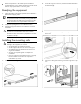
• Electrical requirements—All models require a dedicated (unshared) branch circuit, suitably rated for the specific UPS as stated in "Input specifications" in the user guide. 2. Loosen the wing nuts or hex nuts, and then extend the brackets to the desired length. 3. Use the cage nut tool to install cage nuts or clip nuts into the rear of the rack. 4. Insert screws through the mounting rail into the cage nuts or clip nuts. Readying the equipment 1.
5. Use the cage nut tool to install cage nuts or clip nuts into the front of the rack. 6. Insert a screw through the bottom hole of the mounting rail into the cage nuts or clip nuts. 7. Tighten the wing nuts or hex nuts. 2. Attach the chassis to the rack using the supplied screws. 3. (optional) Insert the rear stabilization brackets into the mounting rails and then attach the brackets to the UPS.
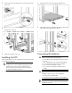
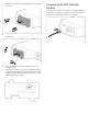
NOTE: A small amount of arcing may occur when connecting the batteries. This is normal and does not damage the unit or present any safety concern. Connect the battery lead to the battery terminal.
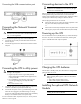
Connecting the USB communications port Connecting devices to the UPS CAUTION: Do not plug laser printers into the UPS output receptacles. The instantaneous current drawn by this type of printer can overload the UPS. Before connecting devices, verify that the UPS will not overload by checking that the ratings of the devices do not exceed the UPS capacity. If the equipment rating is listed in amps, multiply the number of amps by the selected output voltage to determine the VA.
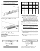
1. Remove the two screws securing the UPS option slot cover plate and remove. Connecting the UPS Network Module The UPS Network Module card is provided to manage the attached servers. RJ 45 network patch panel cables are required to use this card. The RJ 45 network patch panel cables are not included. 2. Install the UPS Network Module along the alignment channels in the option slot. 3. Secure the UPS Network Module using the two screws you removed in step 1. 4.
© Copyright 2011 Hewlett-Packard Development Company, L.P. The information contained herein is subject to change without notice. The only warranties for HP products and services are set forth in the express warranty statements accompanying such products and services. Nothing herein should be construed as constituting an additional warranty. HP shall not be liable for technical or editorial errors or omissions contained herein.