
HP UPS R5000 Installation Instructions

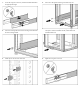
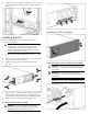
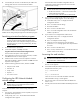
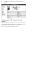
Table Of Contents
- HP UPS R5000 Installation Instructions
- Translated instructions
- Traductions des présentes instructions
- Übersetzungen dieser Anweisungen
- Traduzioni di queste istruzioni
- Traducción de estas instrucciones
- Overview
- Precautions
- UPS kit contents
- Tools and materials
- Selecting a site
- Readying the equipment
- Installing the mounting rails
- Installing the UPS
- Connecting the battery leads
- Attaching the UPS front bezel
- Connecting the serial communications port
- Connecting the USB communications port
- Connecting the REPO port
- Connecting the ground bonding cable
- Connecting the network cable
- Connecting the UPS to utility power
- Connecting devices to the UPS
- Connecting the UPS cord retention clips
- Charging the UPS batteries
- Starting power to the load
- Configuring the UPS Network Module
2. Connect the RJ-45 connector on the DB-9 to RJ-45 cable to the
Settings/AUX connector on the UPS Network Module.
This connection is used to access and configure the UPS Network
Module network settings locally through a terminal emulation program.
Launching a terminal emulation program
NOTE: HyperTerminal is the serial communication
program provided with Microsoft® Windows® and is
used in this section as an example for setting up a terminal
emulation session. If you are using another utility, the steps
might be different.
1. Be sure that the UPS is powered on.
2. On the host computer, click Start, and select
Programs>Accessories>Communications>HyperTerminal.
The Connection Description window appears.
3. Enter a description, select an icon for the connection, and then
click OK. The Connect To window appears.
4. Select the serial connector on the host computer to which the
DB-9 to RJ-45 adapter is attached, and then click OK. The COM
Properties window appears.
5. Select the following parameter values, and then click OK.
o Bits per second—9600
o Data bits—8
o Parity—None
o Stop bits—1
o Flow control—None
Configuring the UPS Network Module
network settings
IMPORTANT: Do not install the existing HP Management
Module software. Only install the HP Power Protector
software required for this unit.
On the terminal emulation session screen running on the host
computer:
1. Press any key. The initialization process completes, and you are
prompted enter the password.
2. At the prompt, enter admin. The HP UPS Network Module
Configuration Menu appears.
Use the HP UPS Network Module Configuration Menu to
configure the minimum settings required to access the UPS
Network Module remotely.
IMPORTANT: The IP address assigned to the UPS
Network Module must be fixed. If the IP address changes:
• The HP Power Protector — Client loses communication
with the UPS Network Module.
• You can lose track of the UPS Network Module URL.
3. If your network is configured with a DHCP server, the network
settings are automatically assigned. To view the settings:
a. On the Main menu, enter 2 to display the Network
Configuration submenu.
b. Enter 1 to read the network settings.
c. Record the IP address.
d. Enter 0 to return to the Main menu.
e. Enter 0 to exit the Configuration Menu. The UPS Network
Module is operational.
4. If your network is not configured with a DHCP server:
a. On the Main menu, enter 2 to display the Network
Configuration submenu.
b. Enter 2 to modify the network settings.
c. Follow the on-screen instructions to enter the static IP
parameters. A Done message appears when the parameters
are saved.
d. Enter 0 to return to the Main menu.
e. Enter 1 to reset, and then enter 2 to restart the UPS Network
Module with the new IP settings.
Accessing the web interface
CAUTION: It is highly recommended that browser access
to the UPS Network Module is isolated from outside access
using a firewall or isolated network.
1. On a network computer, launch a supported browser. The
browser window appears.
2. In the Address field (Microsoft Internet Explorer) or the Location
field (Mozilla and Firefox), enter:
http://xxx.xxx.xxx.xxx
-or-
https://xxx.xxx.xxx.xxx
where xxx.xxx.xxx.xxx is the static IP address of the UPS
Network Module. The log in screen appears.
3. Enter the user name in the User Name field. The default user
name is admin.
4. Enter the password in the Password field. The default password is
admin.