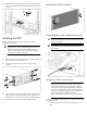
HP UPS R7000 Installation Instructions Part Number 637910-001
Traducción de estas instrucciones Existen versiones traducidas de estas instrucciones disponibles en la documentación proporcionada en la página de soporte del producto específico del sitio web de HP (http://www.hp.com/support/UPSR7000_Manuals). (http://www.hp.com/support/UPSR7000_Manuals) Overview The HP UPS R7000 features a 4U rack-mount design and offers power protection for loads up to 7200 VA/7200 W (NA/JPN) or 6500 VA/6500 W (INTL).
NOTE: The rating label on the device provides the class (A or B) of the equipment. Class B devices have a Federal Communications Commission (FCC) logo or FCC ID on the label. Class A devices do not have an FCC logo or FCC ID on the label. After determining the class of the device, refer to the user guide for complete regulatory compliance notices. than room ambient temperature. Install the equipment in an environment compatible with the operating temperature.
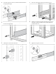
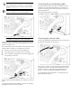
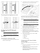
. Loosen the wing nuts or hex nuts, and then extend the brackets to the appropriate length. 5. Insert screws through the rack into the mounting rail and the front of each mounting bracket. 6. Install clip nuts into the rear of the rack. 7. Insert screws through the mounting rail into the clip nuts. 8. Install the rail reinforcement plates and tighten using hex nuts with captive washers included in the kit, instead of the nuts included with the rail. 9. Tighten the wing nuts or hex nuts.
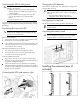
10. Install the rear mounting brackets using hex nuts. Wait until the unit is installed and the brackets are adjusted before tightening the nuts. Installing the UPS Attaching the UPS front bezel Connecting the serial communications port CAUTION: Use only the computer interface cable supplied with the UPS to connect the communications port to the host computer. Before installing the UPS, review and observe all warnings in "Precautions (on page 2).
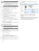
2. For Windows Vista, click Start, select Control Panel, double-click System and Maintenance, and then skip to step 4. -orFor Windows XP, click Start, select Control Panel, click Performance and Maintenance, and then click System. -orFor Windows Server, click Start, select Control Panel, and then double-click System. 3. To reassign a device from COM 1 to another port: 1. From the open Device Manager screen, locate the USB device that is assigned to COM 1. 2. Double-click the port name.
WARNING: To meet the requirements stated in NEC (NFPA 70) Articles 645-10 and 645-11, a UPS installed in a computer equipment room must be connected to a REPO circuit. IMPORTANT: The remote switch must be in the Off (open) position to enable power to the output receptacles. NOTE: Wire the connector block using stranded, nonshielded wire (AWG #22 - #18, or equivalent). Separate wire pairs are attached to a single, normally-open contact in a parallel connection.
Connecting the UPS to utility power WARNING: To prevent injury from electric shock or damage to the equipment: • • • Plug the input line cord into a grounded (earthed) electrical outlet that is installed near the equipment and is easily accessible. Do not disable the grounding plug on the input line cord. The grounding plug is an important safety feature. Do not use extension cords. Connect the UPS to a grounded utility power outlet.
2. Connect the RJ-45 connector on the DB-9 to RJ-45 cable to the Settings/AUX connector on the UPS Network Module. Connecting and securing the power cords This connection is used to access and configure the UPS Network Module network settings locally through a terminal emulation program. Launching a terminal emulation program NOTE: HyperTerminal is the serial communication program provided with Microsoft® Windows® and is used in this section as an example for setting up a terminal emulation session.
IMPORTANT: The IP address assigned to the UPS Network Module must be fixed. If the IP address changes: • • 3. 5. Click Sign In. The HP UPS Network Module web interface appears. The HP Power Protector — Client loses communication with the UPS Network Module. You can lose track of the UPS Network Module URL. If your network is configured with a DHCP server, the network settings are automatically assigned. To view the settings: a. On the Main menu, enter 2 to display the Network Configuration submenu. b.
© Copyright 2011 Hewlett-Packard Development Company, L.P. The information contained herein is subject to change without notice. The only warranties for HP products and services are set forth in the express warranty statements accompanying such products and services. Nothing herein should be construed as constituting an additional warranty. HP shall not be liable for technical or editorial errors or omissions contained herein. Microsoft®, Windows®, and Windows Server® are U.S.