HP UPS R7000 User Guide Abstract This document includes installation, configuration, and operation information for the HP UPS R7000. This document is for the person who installs and maintains power products. HP assumes you are qualified in the servicing of high-voltage equipment and trained in recognizing hazards in products with hazardous energy levels.
© Copyright 2011, 2013 Hewlett-Packard Development Company, L.P. The information contained herein is subject to change without notice. The only warranties for HP products and services are set forth in the express warranty statements accompanying such products and services. Nothing herein should be construed as constituting an additional warranty. HP shall not be liable for technical or editorial errors or omissions contained herein. Microsoft®, Windows®, Windows Vista®, and Windows Server® are U.S.
Contents Overview ..................................................................................................................................... 6 UPS R7000 overview ................................................................................................................................. 6 UPS R7000 features......................................................................................................................... 6 Important safety information.....................................
Operate mode .............................................................................................................................. 31 Auto-Bypass mode ......................................................................................................................... 31 Configuring the UPS ................................................................................................................................ 32 Changing the language......................................................
Minimum battery runtime .......................................................................................................................... 52 Environmental specifications ..................................................................................................................... 53 REPO port specifications .......................................................................................................................... 53 Spares .....................................................
Overview UPS R7000 overview The HP UPS R7000 features a 4U rackmount design and offers power protection for loads up to 7200 VA/7200 W (NA/JPN) or 6500 VA/6500 W (INTL).
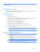
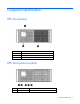
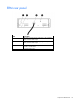
Component identification UPS front panel Item Description 1 LCD display 2 Control buttons 3 Battery compartment UPS front panel controls Item Component Description 1 ESC button Cancel/return to the previous menu Component identification 7
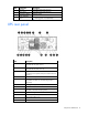
Item Component Description 2 Up arrow Scroll through the menu structure 3 Down arrow Scroll through the menu structure 4 Enter/Select button Select an option 5 Power ON/OFF button • • Green—operating Flashing green—on/off/standby UPS rear panel Item Description 1 Load segment 1 circuit breaker (controls L6-30R receptacle for NA/JPN, Item 3) 2 Load segment 2 circuit breaker (controls L6-30R receptacle for NA/JPN, Item 15) 3 Large output NEMA L6-30R receptacle (NA/JPN) or IEC-320-C19A
Item Description 13 Load segment 2 (3) C19 receptacles 14 Load segment 2 circuit breaker (controls the C19 receptacles, but does not control the large output receptacle) 15 Large output NEMA L6-30R receptacle (NA/JPN) or IEC-320-C19A receptacle (INTL) associated with load segment 2 16 ERM communication port 17 ERM connector for the large plug on the split ERM cable REPO port The UPS includes an isolated REPO port.
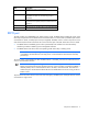
ERM rear panel Item Description 1 ERM input connector for the small plug on the split ERM cable of another ERM output 2 ERM input connector for the large plug on the split ERM cable of another ERM output 3 Split ERM cable with two output connectors that attach to the UPS or another ERM 4 Ground bonding screw Component identification 10
Installation and configuration Precautions Save these instructions. This document contains important safety instructions that should be followed during installation, operation, and maintenance of the UPS and batteries. WARNING: A risk of personal injury from electric shock and hazardous energy levels exists.
• Hex nuts • Cage nuts • Cage nut-fitting tool Selecting a site WARNING: To prevent fire or electric shock, install the unit in a temperature- and humidity-controlled indoor environment, free of conductive contaminants. When selecting a site, consider the following factors: • Elevated operating ambient temperature—If the equipment is installed in a closed or multi-unit rack assembly, the operating ambient temperature of the rack environment might be greater than room ambient temperature.
WARNING: To reduce the risk of personal injury or damage to the equipment, be sure that: • • • • • The leveling feet are extended to the floor. The full weight of the rack rests on the leveling feet. The stabilizing feet are attached to the rack if it is a single-rack installation. The racks are coupled together in multiple-rack installations. Only one component is extended at a time. A rack may become unstable if more than one component is extended for any reason.
3. Install clip nuts into the rear of the rack. 4. Insert screws through the mounting rail into the clip nuts.
5. Install the rail reinforcement plates and tighten using hex nuts with captive washers included in the kit, instead of the nuts included with the rail. 6. Tighten the wing nuts or hex nuts.
7. Install the rear mounting brackets using hex nuts. Wait until the unit is installed and the brackets are adjusted before tightening the nuts. Preparing the rails for integrated shipping If the unit is to be shipped in an HP 9000 or 10000 series rack: 1. Remove the hex nuts, flat washers, and lock washers from the mounting rail. 2. Install the rail reinforcement plates and tighten using the hex nuts with captive washers included in the kit, instead of the nuts included with the rail. 3.
Installing the UPS Before installing the UPS, review and observe all warnings in "Precautions (on page 11)." WARNING: A risk of personal injury or damage to the equipment exists. Uneven loading of equipment in the rack might cause the rack to become unstable. Install the heavier components first, and then continue to populate the rack from the bottom to the top. 1. Install the mounting rails ("Installing the mounting rails" on page 12). 2.
Attaching the UPS front bezel Connecting the serial communications port CAUTION: Use only the computer interface cable supplied with the UPS to connect the communications port to the host computer. IMPORTANT: Power protector software requires the communications port to be appropriately cabled to the host computer.
Configuring a USB to serial converter NOTE: This procedure was tested on the Windows® XP Professional, Windows Server® 2003, and Windows® Vista Enterprise operating systems using the HP USB to serial converter (part number 304098-001). Depending on your system configuration, a driver download might be required to successfully install the converter. The driver can be downloaded from the USB-Drivers website (http://www.usb-drivers.com/drivers/123/123294.htm).
o Bits per second: 9600 o Data Bits: 8 o Parity: None o Stop bits: 1 o Flow control: None 9. Click Advanced. The Advanced Settings screen appears. 10. From the COM Port Number drop down menu, select Com 1 for the USB port number, and then click OK. If COM 1 is being used by another USB port, the following message appears: This COM name is being used by another device. Using duplicate names can lead to inaccessible devices and changed settings.
b. Click Scan for hardware changes to refresh the screen and display the changes. Connecting the USB communications port NOTE: This port is only used for firmware upgrades. For additional information, see "Updating the UPS firmware (on page 43)." Connecting the REPO port WARNING: The pins on the REPO port are polarity sensitive. Be sure to verify polarity while connecting the REPO port.
NOTE: Wire the connector block using stranded, nonshielded wire (AWG #22 - #18, or equivalent). Separate wire pairs are attached to a single, normally-open contact in a parallel connection. HP recommends using different colors for the positive and negative wires. If a connector becomes disconnected and is reconnected with reversed polarity, a REPO is initiated. To avoid REPO port disconnect: • Minimize wire strain while connecting the REPO port. • Avoid allowing the wires to hang in the rear of the UPS.
For information about verifying the REPO connection, see "Verifying the REPO port connection (on page 33)". Connecting the ground bonding cable The ground bonding screw is provided as an attachment point for conductors. Use a ground bonding cable if the rack contains any conductors for the purpose of functional grounding or bonding of ungrounded metal parts. The ground bonding cable is not included.
This connection is used to access the UPS Network Module remotely through the web interface. The UPS Network Module also uses the network connection to communicate to the configured HPPP Clients and to facilitate SNMP-based monitoring. To configure the UPS Network Module, see "Configuring the UPS Network Module (on page 25).
Connecting the UPS cord retention clips Charging the UPS batteries With the UPS in Standby mode, allow the batteries to charge before putting the UPS into service. IMPORTANT: Charge the batteries for at least 24 hours before supplying backup power to devices. The batteries charge to: • 80 percent of their capacity within 3 hours • 100 percent of their capacity within 48 hours Starting power to the load Start power to the load by placing the UPS in Operate mode.
2. Connect the RJ-45 connector on the DB-9 to RJ-45 cable to the Settings/AUX connector on the UPS Network Module. This connection is used to access and configure the UPS Network Module network settings locally through a terminal emulation program. Launching a terminal emulation program NOTE: HyperTerminal is the serial communication program provided with Microsoft® Windows® and is used in this section as an example for setting up a terminal emulation session.
2. At the prompt, enter admin. The HP UPS Network Module Configuration Menu appears. Use the HP UPS Network Module Configuration Menu to configure the minimum settings required to access the UPS Network Module remotely. IMPORTANT: The IP address assigned to the UPS Network Module must be fixed. If the IP address changes: • The HPPP Client loses communication with the UPS Network Module. • You can lose track of the UPS Network Module URL. 3.
5. Click Sign In. The HP UPS Network Module web interface appears. Configuring the UPS Network Module settings Use the Settings screens of the HP UPS Network Module web interface to configure the UPS Network Module. For more information, see the HP UPS Network Module User Guide on the HP website (http://www.hp.com/support/HPNM_Manuals). Installing the ERM Before installing the ERM, review and observe all warnings in "Precautions (on page 11).
3. Install the mounting ears on the chassis using the screws provided. 4. With one person on each side, lift the chassis to rail level and slide the chassis on the mounting rails. Be sure that the cleat brackets slide into the channels on the rear stabilization brackets. 5. Attach the chassis to the rack using the supplied screws.
Connecting the ERM to the UPS Connect both ends of the split ERM cable to the ERM connectors on the UPS rear panel. To install additional ERMs, connect both ends of the split ERM cable from the next ERM into the connectors on the rear panel of the previous ERM. Up to four ERM units can be connected. Charging the ERM batteries Connect the UPS to a grounded utility power outlet. When the UPS is plugged in, it automatically enters Standby mode and begins charging the ERM batteries.
UPS operations Modes of operation The UPS has three modes of operation: • Standby mode (on page 31) • Operate mode (on page 31) • Auto-Bypass mode (on page 31) Standby mode In Standby mode: • No power is available at the UPS output receptacles. • The UPS charges the batteries as necessary. The UPS can be placed in Standby mode when the UPS is in Operate mode (on page 31). To place the UPS in Standby mode, press and hold the Power button. Power to the load ceases.
• Over temperature • Output short • Hardware failure Transferring the UPS between modes To transfer between Operate mode and Bypass mode: 1. Press the ESC button to activate the menu options. 2. Press the down arrow to scroll to the Control menu, and then press the Enter button. 3. Press the Enter button to select Go To Bypass Mode. To transfer between Bypass mode and Operate mode: 1. Press the ESC button to activate the menu options. 2.
Main menu Submenu Display information or menu function — Battery status Battery Charging/Floating/Resting, Charge Level, ERM Number, and Runtime Event Log — Displays events and alarms Measurements Output Output watts and VA — Output Output amps and power factor — Output Output voltage and frequency — Input Input voltage and frequency — Battery Battery voltage and percent charge Control Go to Bypass mode Transfers the UPS system to internal Bypass mode When this command is active, t
1. Initiate a REPO by closing the REPO contact. CAUTION: If the polarity is reversed while connecting the REPO port, the UPS powers up normally. 2. Verify proper connection of the REPO port: a. Power up the UPS by pressing the Power button. b. Disconnect the REPO port. c. Reconnect the REPO port. If the polarity is correct, the REPO connectors can be disconnected, and then reconnected, without initiating a REPO. d. Verify that the UPS remains in Operate mode (on page 31). e.
Power management Power Protector software HP Power Protector software ensures maximum power reliability of computer systems through comprehensive control of UPSs. The easy-to-use browser interface enables novice users to configure and manage power protection settings. To download the latest version of HP Power Protector software, see the HP website (http://www.hp.com/go/rackandpower). NOTE: To install and configure the software, see the software user guide.
• Delays reboot by load segment after a power outage to sequence the startup of system components.
Maintenance Removing the UPS front bezel Removing the ERM front bezel Replacing the UPS Network Module This component is hot-swappable and can be replaced without powering down the UPS.
1. (optional) To replace the component with the UPS powered down, refer to "Powering down the UPS (on page 34)." 2. Disconnect all cables attached to the UPS Network Module connectors. 3. Remove the two screws securing the UPS Network Module and slide the module out. To replace the component, reverse the removal procedure. NOTE: Replacing the UPS Network Module might require power management software to be restarted or reconfigured. Replacing the batteries To replace the batteries: 1.
WARNING: To prevent personal injury, prepare the area and observe all materials-handling procedures when transporting a battery module. Battery modules weigh 20 kg (44 lb). NOTE: Replace all battery modules at the same time with the same type of batteries originally installed in the UPS. Battery care and storage guidelines • Minimize the amount of time the UPS uses battery power by matching the UPS configuration with the utility voltage. Refer to "Configuring the UPS (on page 32).
2. Disconnect the battery leads. 3. Remove the UPS battery bracket. 4. Remove the UPS battery modules. IMPORTANT: Do not pull the battery leads when removing or installing the batteries.
To replace the component, reverse the removal procedure. IMPORTANT: Charge the batteries for at least 24 hours before supplying backup power to devices. The batteries charge to: • 80 percent of their capacity within 3 hours • 100 percent of their capacity within 48 hours Replacing the UPS To remove the UPS: 1. Power down all attached load devices. 2. Power down the UPS ("Powering down the UPS" on page 34). 3. Unplug the UPS power cord. 4. Disconnect all cabling. 5. Remove the UPS front bezel.
6. Disconnect the battery leads. 7. Remove the UPS battery bracket.
8. Remove the UPS battery modules. 9. Remove the screws securing the UPS to the rack. 10. Remove the UPS from the rack. To replace the component, reverse the removal procedure. Replacing the ERM To remove the ERM: 1. Disconnect all cabling. 2. Remove the front bezel ("Removing the ERM front bezel" on page 37) on the ERM that is being replaced. 3. Remove the screws securing the ERM to the rack. 4. Remove the ERM from the rack. To replace the component, reverse the removal procedure.
Troubleshooting Alarm troubleshooting This UPS is designed for durable, automatic operation and also to alert you whenever potential operating problems might occur. Usually the alarms shown on the control panel do not mean that the output power is affected. Instead, they are preventive alarms intended to alert you of a possible condition. The following table describes typical alarms and conditions.
Alarm number Alarm name Alarm description Alarm type Notice Alarm 59 Utility Not Present 68 Battery DC Over Voltage 94 To Bypass Command 95 From Bypass Command 143 On Manual Bypass 149 Service Battery 159 Output Overload Level 2 162 Output Overload Level 3 The utility level has fallen below the Utility Not Present threshold. Battery voltage levels have exceeded the maximum allowable limits. A request to transfer to Manual Bypass Mode received from software.
Silencing an audible alarm To silence an alarm, press any button on the front panel display to silence the alarm. If the alarm status changes, the alarm beeps again, overriding the previous alarm silencing. IMPORTANT: • Although the audible alarm silences, the condition that caused the alarm to sound may still exist. • If a utility power failure caused the alarm, the alarm silences after power is restored. For information about audible alarm conditions, see "Alarm troubleshooting (on page 44).
c. Wait at least 5 seconds and restart the UPS. d. If the condition persists, verify that the load devices are not defective. 4. Allow the UPS to cool: a. Power down the UPS ("Powering down the UPS" on page 34). b. Clear vents and remove any heat sources. c. Verify that the airflow around the UPS is not restricted. 5. Wait at least 5 minutes and restart the UPS. 6. If the condition persists, contact an HP authorized service representative. Input voltage is out of range Action: 1.
Action: Remove one or more load devices to reduce the power requirements.The UPS continues to operate, but might switch to Auto-Bypass mode (on page 31) if the load increases. The alarm resets when the conditions becomes inactive. REPO condition Action: • If the remote switch is closed, then open the switch to enable power to the output receptacles. • If the condition occurred while reconnecting a disconnected REPO port, then verify the polarity of the REPO connector pins.
UPS is in Auto-Bypass mode Action: 1. If power management software is being used, check the log files to obtain specific error information to help identify the problem. For more information about the causes of a general fault condition, see the HP Power Manager user guide available for download from the HP website (http://www.hp.com/go/rackandpower). 2. Verify that no blockage of airflow to the front bezel and rear panel exists. UPS is on battery Action: Save files and shut down connected equipment.
Specifications UPS physical specifications Parameter Value Height 17.1 cm (6.75 in) Depth 73.4 cm (28.9 in) Width 43.7 cm (17.2 in) Weight 75 kg (165 lb) Ambient operation 0~40°C ERM physical specifications Parameter Value Height 12.7 cm (5 in) Depth 71.9 cm (28.3 in) Width 43.8 cm (17.24 in) Weight 63 kg (139 lb) UPS input specifications NOTE: An asterisk (*) indicates the default setting.
UPS model Load segment 2 R7000 INTL Circuit breaker 20 A¹ 1 20 A¹ 2 20 A¹ Output receptacles Maximum current 1 x L6-30R Up to full UPS power rating 2 x IEC-320-C19 16 A per receptacle² 2 x IEC-320-C13 10 A per receptacle 2 x IEC-320-C19 16 A per receptacle² 2 x IEC-320-C13 10 A per receptacle 1 x IEC-309-32A Up to full UPS power rating 2 x IEC-320-C19 16 A per receptacle² 2 x IEC-320-C13 10 A per receptacle The circuit breakers protect the C19 and C13 outlets.
Feature Specification Voltage wave shape Sine wave; 5% THD with typical PFC load Surge suppression High-energy 6500 A peak Noise filtering MOVs and line filter for normal and common mode use Battery specifications Feature Specification Type Each model contains maintenance-free, sealed, valve regulated lead-acid batteries with an 8-year minimum float service life at 25°C (77°F). Voltage The battery modules have a battery string voltage of 216 V.
Environmental specifications Feature Specification Operating temperature 10°C to 40°C (50°F to 104°F); UL-tested at 25°C (77°F) Nonoperating temperature -25°C to 55°C (-13°F to 131°F) Relative humidity 20% to 80%; noncondensing Operating altitude Up to 2,000 m (6,600 ft) above sea level Nonoperating altitude 15,000 m (49,212 ft) above sea level Audible noise Less than 50 dBA, normal operation Less than 55 dBA, on battery power REPO port specifications The REPO port meets the requirements of NF
Spares Ordering spares To order a spare, visit the HP website (http://www.hp.com/buy/parts). To replace parts under warranty, contact an HP authorized service representative.
Regulatory information Safety and regulatory compliance For safety, environmental, and regulatory information, see Safety and Compliance Information for Server, Storage, Power, Networking, and Rack Products, available at the HP website (http://www.hp.com/support/Safety-Compliance-EnterpriseProducts). Turkey RoHS material content declaration Ukraine RoHS material content declaration Warranty information HP ProLiant and X86 Servers and Options (http://www.hp.
• The UPS is plugged into a suitably grounded and wired outlet using no extension cords, adapters, other ground wires, or other electrical connections. • The UPS installation complies with all applicable electrical and safety codes specified by the NEC. • The UPS is used under normal operating conditions and users comply with all instructions and labels. • The UPS is not damaged by accident (other than a utility power transient), misuse, or abuse.
Electrostatic discharge Preventing electrostatic discharge To prevent damaging the system, be aware of the precautions you need to follow when setting up the system or handling parts. A discharge of static electricity from a finger or other conductor may damage system boards or other static-sensitive devices. This type of damage may reduce the life expectancy of the device. To prevent electrostatic damage: • Avoid hand contact by transporting and storing products in static-safe containers.
Support and other resources Before you contact HP Be sure to have the following information available before you call HP: • Active Health System log (HP ProLiant Gen8 or later products) Download and have available an Active Health System log for 3 days before the failure was detected. For more information, see the HP iLO 4 User Guide or HP Intelligent Provisioning User Guide on the HP website (http://www.hp.com/go/ilo/docs).
Acronyms and abbreviations ERM extended runtime module IEC International Electrotechnical Commission PDU power distribution unit PFC power factor corrected REPO remote emergency power off RMS root-mean-square UPS uninterruptible power system Acronyms and abbreviations 59
Documentation feedback HP is committed to providing documentation that meets your needs. To help us improve the documentation, send any errors, suggestions, or comments to Documentation Feedback (mailto:docsfeedback@hp.com). Include the document title and part number, version number, or the URL when submitting your feedback.
Index A frequent switching between battery and utility power 48 authorized reseller 58 G B grounding methods 57 backup time, insufficient 48 batteries, care and storage 39 batteries, charging 25, 30 batteries, replacing 38 battery replacement notice 55 battery warranty 55 bezel, removing 37 BSMI notice 55 buttons 7 bypass is out of range 46 H C Canadian notice 55 charging batteries 25, 30 components, identification 7 configuration of system 32 connectors 7 contacting HP 58 D Declaration of Conformi
overview, UPS 6 P phone numbers 58 power management 35 power protection specifications 50 preparation procedures 11 problem diagnosis 44 UPS Network Module 25, 28 UPS operations 31 utility power condition 49 utility power, connecting 24 V voltage specifications 51 R regulatory compliance identification numbers 55 regulatory compliance notices 55 replacing the batteries 38 replacing the ERM 43 REPO condition 48 REPO port, overview 9 REPO port, specifications 53 required information 58 required tools 11