
UPS R12000 XR Backplate Receptacle Kit Installation Instructions


hp r12000 xr
backplate receptacle
kit
installation instructions
Read instructions completely before beginning
installation procedure.
© 2003 Hewlett-Packard Development Company, L.P.
Hewlett-Packard Company shall not be liable for technical or editorial errors or
omissions contained herein. The information in this document is provided “as is”
without warranty of any kind and is subject to change without notice. The warranties
for HP products are set forth in the express limited warranty statements
accompanying such products. Nothing herein should be construed as constituting an
additional warranty.
hp r12000 xr backplate receptacle kit installation instructions
First Edition (February 2003)
Part Number 330871-021
330871- 021
Overview
These instructions assist qualified electricians with the installation
of the HP Backplate Receptacle Kit. Save these instructions for
future reference.
NOTE: This kit can only be used with the HP Uninterruptible Power System
(UPS) R12000 XR model.
Important Safety
Information
Before installing this product, read the Important Safety
Information guide included with this kit.
WARNING:
• The installation of this product must be performed by
individuals who are knowledgeable about the procedures,
precautions, and hazards associated with AC and DC power
products.
• The backplate receptacle option must be connected directly
to the UPS by a qualified electrician.
• The connection of the backplate receptacle option to the
terminals of the UPS must be performed by a qualified
electrician.
• There are no user-serviceable components inside.
Kit Contents
• Backplate receptacle option
• Important Safety Information guide
• This document
Tools and Materials Required
The following tools are needed:
• #3 Phillips screwdriver bit
• Flat-head screwdriver
• Metric tools
— 7 mm
— 8 mm
Powering Down the UPS
WARNING: To reduce the risk of electric shock or personal injury
while performing this procedure, use a Lockout/Tagout
procedure to isolate the UPS from the AC branch circuit (AC
mains). The Lockout/Tagout procedure should conform to local
occupational safety and health regulations for the facility.
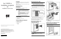
To power down the UPS:
1. Place the UPS in Standby mode by pressing the Standby button
for three seconds. The load relays open, and the Utility LED
(1) begins to flash slowly.
2. Disconnect the AC mains by opening the switch or circuit
breaker at the utility panel and Lockout/Tagout.
NOTE: If installing the UPS for the first time, go to the “Wiring to the
Terminal Block” section of this document. Refer to the installation
instructions for the UPS for more information.
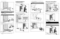
Removing the Battery and
Electronics Modules
1. Remove the front bezel.
27 kg
60 lb
WARNING: To prevent personal injury, prepare the area
and observe all materials-handling procedures for
removing the battery module, which weighs
27 kg (60 lb).
2. Remove the battery module.
3. Remove the electronics module.
4. Repeat steps 1 through 3 to remove the remaining battery and
electronics modules.
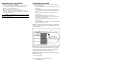
Disconnecting the Batteries in the
Extended Runtime Modules
IMPORTANT: If there is an extended runtime module (ERM) connected to
the UPS, disconnect the ERM batteries.
1. Remove the ERM bezel.