
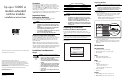
UPS R12000 XR ERM Installation Instructions


Tools and Materials Required
The following tools are needed:
• #3 Phillips screwdriver bit
• Metric tools
— 7 mm
— 8 mm
— 10 mm
— 13 mm
— 14 mm
• Multimeter
The following items are supplied with the HP rack:
• Screws
• Cage nuts
• Cage nut-fitting tool
Unpacking the ERM
Transport the packaged ERM to its installation location. Unpack
the ERM near the rack where it will be assembled. Follow the
unpacking instructions on the carton. Verify that all components
are present.
WARNING: The battery modules are charged from the factory; do
not touch the metal contacts inside the connector.
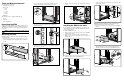
Mounting the Rails
The ERM must be mounted on the fixed rails supplied in this kit.
To mount the rails:
1. Loosen the wing nuts (1) and extend the brackets (2) to the
desired length. Tighten the wing nuts slightly to stabilize the
bracket.
2
1
2. Use the rack template tool to measure and mark the screw
locations for the rails on the front and rear of the rack.
3. Use the cage nut tool to install the cage nuts in the rear
rack-mounting rails.
4. Insert at least one screw through each rack-mounting rail and
into the front of each rail.
5. Insert the back screws into the cage nuts that were installed in
step 3.
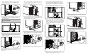
Installing the ERM in the Rack
Before attempting to install the ERM, review and adhere to all
safety information provided in the "Installation Considerations"
section of this document.
To install the ERM in the rack:
1. With one person on each side of the carton, remove the ERM
chassis from the carton.
2. Gently lower the chassis to the floor in front of the rack.
3. With one person on each side, lift the chassis to rail level and
slide into place.
4. Remove the front panel from the ERM chassis.
5. Secure the chassis to the rack using the screws and cage nuts
supplied with the rack.
NOTE: After installing the ERM chassis, insert remaining screws for
additional support, if any screw holes are unoccupied.
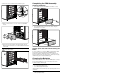
6. Remove the electrical access cover on the rear of the ERM
chassis.
7. Insert the left battery module (1) and connect the battery
module connector to the connector in the ERM chassis (2).
1
2