
UPS R12000 XR ERM Installation Instructions

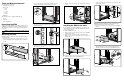


8. Insert the right battery module (1) and connect the battery
module connector to the connector in the ERM chassis (2)
through the rear opening.
2
1
9. Verify the polarity of the DC voltage using a multimeter
between terminals, positive (1) and negative (2), before wiring
the ERM to the UPS.
WARNING: If the polarity is reversed, contact HP for
replacement of the ERM.
1 2
10. Disconnect the two battery module connectors to the ERM,
first the left battery module and then the right battery module,
through the rear opening.
NOTE: Refer to the UPS installation instructions for directions on how to
assemble the UPS.
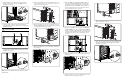
11. Remove the terminal block cover from the UPS. Remove the
screws (1), release the cover (2), and remove the cover (3). Set
aside, but do not discard the cover.
1
2
1
3
12. Remove the wiring port cover (2) by removing the screws (1).
The UPS-to-ERM wiring port cover will drop out of the bottom
of the UPS when the screws are removed.
2
1
1
13. Remove the DC bus bar cover (2) of the UPS by unfastening
the four nuts (1).
2
1
14. Connect the ERM to the UPS with the ERM-to-UPS power
cable set included with the ERM kit. In order, connect the
green/yellow cable (1) and torque the nut to 25 in-lbs (A) on
the UPS and 75 in-lbs on the ERM (B). Connect the black
cable (2) and torque the nuts to 160 in-lbs. Connect the red
cable (3) and torque the nuts to 160 in-lbs.
1
A
B
3 2
15. Connect a second ERM (if necessary) to the first ERM using
the ERM-to-ERM power cable set included with the ERM kit.
In order, connect the green/yellow cable (1) and torque the nut
to 75 in-lbs. Connect the black cable (2) and torque the nuts to
160 in-lbs. Connect the red cable (3) and torque the nuts to
160 in-lbs.
3 1 2
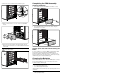
16. Replace the DC bus bar cover (1) of the UPS by tightening the
four nuts (2).
1
2
17. Replace the wiring port cover on the UPS. Insert the screw (1)
first, then insert the remaining two screws (2).
1
2
18. Replace the terminal block cover on the UPS (1), sliding it into
place (2). Tighten the screws (3).
3
2
3
1
19. Connect the two battery module connectors to the ERM, first
the left battery module and then the right battery module,
through the rear opening.