
UPS R12000 XR Models Installation Instructions


hp uninterruptible
power system r12000
xr models
installation instructions
Read instructions completely before beginning
installation procedure.
© 2003 Hewlett-Packard Development Company, L.P.
Hewlett-Packard Company shall not be liable for technical or editorial errors or
omissions contained herein. The information in this document is provided “as is”
without warranty of any kind and is subject to change without notice. The warranties
for HP products are set forth in the express limited warranty statements
accompanying such products. Nothing herein should be construed as constituting an
additional warranty.
hp uninterruptible power system r12000 xr models installation instructions
Second Edition (December 2002)
Part Number 146305-002
146305- 002
Overview
These instructions show how to install an uninterruptible power
system (UPS). For detailed information about the UPS, refer to the
UPS user guide on the Power Products Documentation CD.
These instructions assist qualified personnel with the installation of
the HP UPS. Save these instructions for future reference.
Use the UPS R12000 XR Installation and Startup Package to
facilitate the installation and startup of the UPS.
Table 1: Installation and Startup Package Numbers
Location Package Number
United States FM-BPINS-IN
Worldwide FP-UPSXR-IN
Important Safety Information
Before installing this product, read the Important Safety
Information guide included with the UPS kit.
Regulatory Compliance
Information Numbers
For regulatory compliance certifications and identification
purposes, the UPS models are assigned a series number, also
identified on the Regulatory Compliance label located on the side
of the UPS. For certification information, always refer to the series
number EO3002 and PDU series number EO3024.
NOTE: The rating label on the device provides the class (A or B) of the
equipment. Class B devices have a Federal Communications Commission
(FCC) logo or FCC ID on the label. Class A devices do not have an FCC logo
or FCC ID on the label. After you determine the class of the device, refer to
the UPS user guide for complete regulatory compliance notices.
Installation Considerations
Weight
190 kg
420 lb
WARNING: To reduce the risk of personal injury or
damage to the equipment:
• Have the floor-loading requirements evaluated by a
facilities engineer before installation.
• Observe local occupational health and safety
requirements and guidelines for manual material
handling.
• Obtain adequate assistance to lift and stabilize the
product during installation or removal. The UPS
will be unstable when not fastened to the rails.
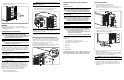
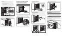
• Remove all batteries and electronics modules to
reduce the overall weight of the UPS chassis.
• Use three people to lift and place the UPS in the
rack.
Table 2: Component Weights
Component Weight
Chassis 43 kg (95 lb)
Electronics modules (4) 9.5 kg (21 lb) each
Battery modules (4) 27 kg (60 lb) each
Fully assembled UPS 190 kg (420 lb)
Position
WARNING: To reduce the risk of personal injury or damage
to the equipment, take the following precautions when
installing the equipment:
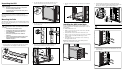
• The UPS must be installed at the bottom of the rack. If
placed in the rack with existing equipment, the rack
must be reconfigured to allow installation of the UPS at
the bottom of the rack.
• The UPS must be mounted on the rails included in the
UPS kit. Use the rack template tool included in the UPS
kit to align the rails.
Preparing for Installation
Preparing the Site
Due to the weight of this device, do not proceed until a facilities
engineer evaluates and approves the floor-loading requirements
before installation.
Checking the Battery Recharge Date
Before unpacking the UPS, check the battery recharge date
specified on the battery recharge date label that is affixed to the
shipping carton.
IMPORTANT: Do not use the batteries if the recharge date has passed. If
the date on the battery recharge date label has passed without the batteries
being recharged, contact an HP authorized service representative for
directions.
NOTE: The following label is only an example date. The date on your carton
may be different.
THIS PRODUCT CONTAINS
A NONSPILLABLE BATTERY
Next Recharge Date:
Please refer to Maintenance Section
of Owner's Manual enclosed inside
05-MAR-07
Kit Contents
Documentation
• International Regulatory Compliance guide
• Important Safety Information guide
• Power Products Documentation CD
• Rack and Power Management Pack CD
• This document
Rails
• Rails, with mounting hardware
• Rack template tool 10U (221280-021)
UPS
• UPS chassis
• Four electronics modules
• Four battery modules
• Five front bezel pieces
• Hardware
— M6 x 12 hex bolt (2)
— M6-1 x 12.0 cross recessed screw (20)
— M6 hex nut with conical washer (3)
Cable
One 3.7-m (12-ft) communication cable (201092-002)
Power Distribution Unit (PDU) Option Kit
• 40 A 200–240 V WW Model PDU
• PDU installation instructions
Tools and Materials Required
The following tools are needed:
• Medium flat-bladed screwdriver
• #1 Phillips screwdriver bit
• #3 Phillips screwdriver bit
• Metric tools
— 7-mm
— 8-mm
— 10-mm
• Sheetmetal hole punch tools, up to 44.45 mm (1.75 inches)
in diameter
The following items are supplied with the HP rack:
• Screws
• Cage nuts
• Cage nut-fitting tool