
UPS R12000 XR Models Installation Instructions


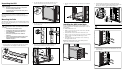


8. Attach the hold-down bracket to the rack rail with the screws
included in the hardware kit.
Wiring
Refer to Table 1 in "Overview" for details regarding the
Installation and Startup Package, which is used to simplify setup
and installation of the UPS.
Code Compliance Information
WARNING: The UPS requires a direct connection to a dedicated
AC branch circuit (AC mains). Connection should only be
performed by a qualified electrician in accordance with National
Electrical Code (NFPA 70) Article 310 in North America or in the
equivalent local and national wiring regulations.
WARNING: If the UPS is to be installed in a server equipment
room, it must be connected to a REPO circuit. The REPO port is
designed to meet the requirements stated in National Electrical
Code (NFPA 70) Articles 645-10 and 11.
Connecting the REPO Port
The UPS includes a REPO port. When properly wired, the REPO
port allows the power at the UPS output receptacles to be switched
off from a remote location. Local or national wiring regulations
may require REPO capabilities.
WARNING: To reduce risk of personal injury or damage to
equipment, the REPO port must be wired by a qualified
electrician.
WARNING: Remote circuits connected to the REPO port must
comply with local building wiring codes and methods. In North
America, the National Electric Code (NFPA 70, Article 725) is a
minimum requirement.
The UPS REPO circuit is an IEC950 Secondary Extra Low
Voltage (SELV) circuit. The computer room Emergency Power
shutdown circuit conductors that connect to the REPO terminals
must meet the requirements of an NEC Class 2 circuit or an
IEC950 SELV circuit and must be separated from any hazardous
voltage circuits or conductors by reinforced insulation.
The server room Emergency Power shutdown circuit must:
• Short the UPS REPO terminals.
• Disconnect the UPS AC input source.
WARNING: To avoid risk of personal injury or electric shock,
verify that the main breaker switch is in the Off position before
wiring the REPO port.
To connect the REPO port to the EPO circuit:
1. Verify that the UPS is disconnected from utility power.
2. Connect the switch or circuit to the REPO port.
IMPORTANT: The cable that connects the UPS to the REPO port must be
UL Listed, of type CL2, CL2P, CL2R, or CL2X, depending on the
requirements of the local installation.
3. Verify that the Remote Circuit is off. Be sure the REPO switch
is in the Off (open) position to enable power to the UPS output.
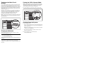
Connecting the Ground Bonding Screw
The ground bonding screw on the rear of the unit is provided as an
attachment point for conductors. Use the ground bonding screw if
the rack contains any conductors for the purpose of functional
grounding or bonding of ungrounded metal parts.
To connect the ground bonding screw:
Remove the ground bonding screw nut (1), attach the grounding
cable, and secure the ground bonding screw nut (2).
2
1
Connecting the UPS to the AC Branch
Circuit
Risk of Fire Notice
WARNING: To reduce the risk of fire, only connect the UPS to a
circuit provided with a 100 A maximum branch circuit rated
overcurrent protection device in accordance with the National
Electrical Code (NFPA 70) and Canadian Electrical Code, C22.1.
Electrical Safety
WARNING: To reduce the risk of electrical shock or personal
injury while performing this procedure, use a Lockout/Tagout
procedure to isolate the UPS from the AC branch circuit (AC
mains). The Lockout/Tagout procedure should conform to local
occupational health and safety regulations for the facility.
WARNING: The UPS must be connected to a circuit provided
with a 100 A maximum branch circuit rated overcurrent
protection.
WARNING: The installation of options and routine maintenance
and service of this product must be performed by individuals
who are knowledgeable about the procedures, precautions, and
hazards associated with AC power products.
• The UPS must be connected directly to the AC branch circuit
(AC mains) by a qualified electrician.
• There are no user-serviceable components inside the UPS.
Requirements
The UPS requires a dedicated branch circuit meeting the following
requirements:
• 100 A circuit with overcurrent protection
• An appropriate and readily accessible disconnect device
incorporated in the fixed wiring
• 200-240 V
• Single phase
• 50-60 Hz
Recommendation
Conduit must be used in accordance with local electrical codes
when hardwiring the UPS. Contact a qualified electrician for
UPS and option installation and for input and output loads.
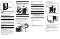
Connecting the UPS
To connect the UPS to the AC branch circuit:
1. Locate the input/output terminal block cover.
2. Remove the terminal block cover. Remove the screws (1),
release the cover (2), and remove the cover (3). Set aside, but
do not discard the cover.
1
2
1
3
3. Remove the wiring port cover (1).
4. Using locator marks on the cover, punch out necessary access
points for the input and output wiring (2).
1
1
2
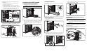
5. Replace the wiring port cover.
6. Pull the wires through the conduit leading from the AC mains,
leaving about 0.5 m (2 ft) of wire hanging from the end. Attach
a suitable connector to the end of the conduit.
WARNING: To reduce the risk of personal injury from fire or
shock, use only 75°
°°
°C (167°
°°
°F) or higher rated wire.
7. Feed the wires through the wiring entry port, the entry
compartment, and the terminal input block compartment.
8. Connect the conduit to the panel. Measure the wires and cut
and strip 1.25 cm (0.5 in) of insulation from the end of each
incoming wire.