
UPS R1500 XR Models Installation Instructions


Electrical Requirements
All UPS models require a dedicated (unshared) branch circuit,
suitably rated for your specific UPS model as follows:
• 20 A for low-voltage R1500 XR JPN
• 15 A for low-voltage R1500 XR NA
• 10 A for high-voltage R1500 XR H INT’L
WARNING: To prevent fire or electric shock, install the UPS in a
temperature- and humidity-controlled indoor environment, free
of conductive contaminants.
WARNING: Risk of personal injury from electric shock. The UPS
R1500 XR H INT’L model is not suitable for installation where
the total earth (ground) conductor leakage current for all
connected devices exceeds 3.5 mA. You may use RackBuilder
Pro (obtainable from www.hp.com) to find the total system
leakage current.
IMPORTANT: If the UPS does not include a suitable power cord, contact an
HP authorized service representative to obtain the appropriate power cord.
Preparing for Installation
Unpacking the UPS
Transport the packaged UPS to its installation location. Unpack the
UPS near the rack where it will be assembled. Follow the
unpacking instructions on the carton.
Mounting the Rails
The UPS must be mounted on the fixed rails supplied with the
UPS. Before beginning this installation process, review and adhere
to the following precautions.
WARNING: To prevent personal injury, verify that the rack
containing the UPS is stable. The following conditions must be
met:
• The leveling feet are extended to the floor.
• The full weight of the rack rests on the leveling feet.
• The stabilizing feet are attached to the rack if it is a
single-rack installation.
• The racks are coupled together if it is a multi-rack
installation.
• Only one component should be extended at a time. A rack
may become unstable if more than one component is
extended for any reason.
IMPORTANT: Power down the UPS to safely perform the following tasks.
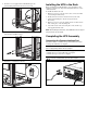
To mount the rails:
1. Loosen the wing nuts (1) and extend the brackets to the desired
length (2). Tighten the wing nuts slightly to stabilize
the bracket.
1
2
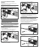
2. Use the rack template tool to measure and mark the screw
locations on the front and rear of the rack.
3. Use the cage nut tool to install the cage nuts in the rear
rack-mounting rails.