
UPS R3000 XR Models Installation Instructions

Connecting the UPS to Utility Power
Connect the UPS to a grounded utility power outlet.
WARNING: To prevent personal injury from electric shock or
damage to the equipment:
• Plug the input line cord into a grounded (earthed) electrical
outlet that is installed near the equipment and is easily
accessible.
• Do not disable the grounding plug on the input line cord. The
grounding plug is an important safety feature.
• Do not use extension cords.
Connecting Devices to the UPS
Before connecting devices, verify the UPS will not overload by
checking that the ratings of the devices do not exceed the UPS
capacity. Evenly distribute connected devices throughout all load
segments.
After verifying that the UPS will not overload, connect the power
cords from the devices to the appropriate output receptacles of the
UPS.
CAUTION: Do not plug laser printers into the UPS. The
instantaneous current drawn by this type of printer can overload
the UPS.
IMPORTANT: To provide additional receptacles, plug a Power Distribution
Unit (PDU) into the high-current receptacle associated with load segment 1.
Refer to the UPS user guide for a list of supported PDUs.
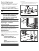
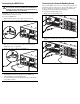
Connecting Cord Retention Clips
Insert the cord retention clip (included with this kit) into the
attachment location (1). Stabilize connected device cords by
fastening (twisting) the cord retention clip (2).
NOTE: UPS appearance may vary depending on the specific unit installed.
1
2
Powering Up the UPS
To power up the UPS:
1. Connect the UPS to utility power using the input power cord.
The UPS automatically initiates a self-test. If the self-test is
completed successfully, the UPS enters Standby mode.
2. Check the front panel LED display. The Utility LED should be
flashing green. The load segments are not energized.
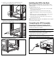
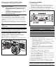
11 A
1
2
3
15
14
13
4
5
6
7
9
10
8
12
1 General Alarm 9 26% to 50% load
2 On Battery 10 0% to 25% load
3 Bad Battery 11 Configure Mode On LED
4 Site Wiring Fault Indicator 12 Configure button
5 Utility LED 13 Test/Alarm Reset button
6 Overload LED 14 Standby button
7 76% to 100% load 15 On button
8 51% to 75% load A Voltage configuration panel
• Utility LED (5):
Red – UPS is in Auto-Bypass mode.
Flashing Red – Utility input voltage is outside the ±12%
configured nominal range.
Green – Utility voltage is present and output is on or utility
voltage has returned to the voltage range that was
configured (UPS is supplying utility power and audible
alarm should be reset).
Flashing Green – Utility voltage is present and UPS is in
Standby mode. Output is off. Batteries charge if needed.
• Overload LED (6): Red – UPS load exceeds maximum power
available.
• 76% to 100% load LED (7): Green – UPS load is
approximately 76% to 100% of maximum power.
• 51% to 75% load LED (8): Green – UPS load is approximately
51% to 75% of maximum power.
• 26% to 50% load LED (9): Green – UPS load is approximately
26% to 50% of maximum power.
• 0% to 25% load LED (10): Green – UPS load is approximately
0% to 25% of maximum power.
Refer to the UPS user guide for more information on the front
panel LED display and for procedures on configuring the UPS.
IMPORTANT: If any of the front panel LEDs is red (indicating an alarm
condition), press the Test/Alarm Reset button to clear the red LEDs. If this
does not clear the LEDs, refer to the UPS user guide for more information.