
UPS R3000 XR Models User Guide

Configuration
3-2 HP Uninterruptible Power System R3000 XR Models User Guide
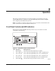
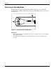
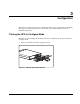
2. Press and hold the Configure button (1) for three seconds. When the button is released,
the front panel configuration parameters flash in unison and the Configure Mode On LED
(2) illuminates solid green.
1
2
Figure 3-2: Placing the UPS in Configure mode
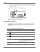
Configuration Parameters
In Configure mode, the front panel LED display changes function to allow UPS monitoring.
The LED button controls allow modification of the UPS configuration parameters. The
configuration parameters are defined in Table 3-1. Available voltage settings per model are
listed in Table 3-2.
Table 3-1: Configuration Parameters/LED Indicators
Parameter (LED) Parameter Name Explanation (when illuminated)
General Alarm
100/200-208 Nom Nominal utility voltage level is 100/200-208 VAC.
On Battery
110/220 Nom Nominal utility voltage level is 110/220 VAC.
Bad Battery/Low
Battery
120/230 Nom Nominal utility voltage level is 120/230 VAC.
Site Wiring Fault
Indicator
127/240 Nom Nominal utility voltage level is 127/240 VAC.
Utility LED
Wiring
Fault
Audible alarm is enabled if ground is missing, or if line
and neutral connections are reversed. (This option is not
available on the R3000j XR-JPN, R3000h XR-NA, and
R3000h XR-JPN models.)
Note: For units factory-configured for 200 V or 208 V, the Site Wiring Fault function has been
disabled. If reconfiguring a 230 V to operate at 208 V, the Site Wiring Fault function must be manually
disabled.