
UPS R6000 Models Installation Instructions


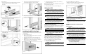


To mount the rails:
1. Loosen the wing nuts (1) and extend the brackets to the desired
length (2). Tighten the wing nuts slightly to stabilize
the bracket.
2. Use the rack template tool to measure and mark the screw
locations on the front and rear of the rack.
3. Use the cage nut tool to install the cage nuts in the rear
rack-mounting rails.
4. Insert the screws supplied in the UPS kit through each
rack-mounting rail and into the front of each rack.
5. Insert the screws into the back of each rail and through the cage
nuts that were installed in step 3.
Installing the UPS in the Rack
Before attempting to install the UPS, review and adhere to all
warnings provided in the “Important Safety Information” section
of this document.
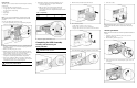
To install the UPS in the rack:
1. With one person on each side of the carton, remove the UPS
chassis using the lift-out tray.
2. Gently lower the chassis to the floor in front of the rack.
3. Cut the band holding the chassis, freeing the UPS from the
lift-out tray.
4. With one person on each side, lift the chassis to rail level and
slide the UPS into place on the mounting rail.
5. Attach the chassis to the rack using the screws and the cage
nuts supplied with the rack.
NOTE: After installing the UPS chassis, insert additional screws for support
if any screw holes are unoccupied.
6. Verify that the UPS is disconnected from utility power.
Wiring the UPS
WARNING: To prevent personal injury, use a Lockout/Tagout
procedure to isolate the UPS from the AC branch circuit
(AC mains). The Lockout/Tagout procedure should conform to
local occupational safety and health regulations for the facility.
Code Compliance Information
WARNING: The UPS requires a direct connection to a dedicated
AC branch circuit (AC mains). Connection should only be
performed by a licensed electrician in accordance with National
Electrical Code (NFPA 70) Article 310 in North America or in the
equivalent local and national wiring regulations.
WARNING: If the UPS is to be installed in a computer equipment
room, it must also be connected to a REPO circuit. The REPO
port is designed to meet the requirements stated in National
Electrical Code (NFPA 70) Articles 645-10 and 11.
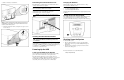
Connecting the REPO Port
The UPS includes a REPO port. When properly wired, the REPO
port allows the power at the UPS output receptacles to be switched
off from a remote location. Local or national wiring regulations
may require REPO capabilities.
WARNING: To prevent personal injury or damage to equipment,
the REPO port must be wired by a qualified electrician.
WARNING: Remote circuits connected to the REPO port must
comply with local building wiring codes and methods. In North
America, the National Electric Code (NFPA 70, Article 725) is a
minimum requirement.
The UPS REPO circuit is an IEC950 Secondary Extra Low
Voltage (SELV) circuit. The server room Emergency Power
shutdown circuit conductors that connect to the REPO terminals
must meet the requirements of an NEC Class 2 circuit or an
IEC950 SELV circuit and must be separated from any hazardous
voltage circuits or conductors by reinforced insulation.
The server room Emergency Power shutdown circuit must:
• Short the UPS REPO terminals.
• Disconnect the UPS AC input source.
WARNING: To prevent personal injury from electric shock, verify
that the main breaker switch is in the off position before wiring
the REPO port.
To connect the REPO port to the EPO circuit:
1. Make sure that the UPS is disconnected from utility power.
2. Connect the switch or circuit to the REPO port.
IMPORTANT: The cable that connects the UPS to the REPO port must be
UL Listed, of type CL2, CL2P, CL2R, or CL2X, depending on the
requirements of the local installation.
3. Verify that the Remote Circuit is off. Make sure the REPO
switch is in the off (open) position to enable power to the UPS
output.
Connecting the UPS to the AC Branch
Circuit
Risk of Fire Notice
WARNING: To reduce the risk of fire, only connect the UPS to a
circuit provided with a 40 A maximum branch circuit rated
overcurrent protection device in accordance with the National
Electrical Code (NFPA 70) and Canadian Electrical Code, C22.1.
Electrical Safety
WARNING: To reduce the risk of electrical shock or personal
injury while performing this procedure, use a Lockout/Tagout
procedure to isolate the UPS from the AC branch circuit (AC
mains). The Lockout/Tagout procedure should conform to local
occupational health and safety regulations for the facility.
WARNING: The installation of options and routine maintenance
and service of this product must be performed by individuals
who are knowledgeable about the procedures, precautions, and
hazards associated with AC power products.
• The UPS must be connected directly to the AC branch circuit
(AC mains) by a qualified electrician.
• There are no user-serviceable components inside the UPS.