
UPS R6000 Models Installation Instructions


Requirements
The UPS requires a dedicated branch circuit meeting the following
requirements:
• 40 A circuit with overcurrent protection
• An appropriate and readily accessible disconnect device
incorporated in the fixed wiring
• 200-240 V
• Single phase
• 50-60 Hz
NOTE: For ease of service and maintenance, use flexible metal conduit
when hardwiring the UPS. Consult a licensed electrician to perform this
procedure.
To connect the UPS to the AC branch circuit:
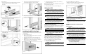
1. Locate the input wiring entry port (1), input wiring inspection
panel (2), and input terminal block cover (3).
2. Remove the input terminal block cover (3). Set aside but do not
discard the cover. The cover carries the wiring diagram for the
input terminal block.
3. Remove the wiring entry port cover (1).
4. Pull the input wires through the conduit leading from the AC
mains, leaving about 0.5 m (2 ft) of wire hanging from the end.
Attach a suitable connector to the end of the conduit.
5. Feed the wires through the input wiring entry port, the entry
compartment, and the input terminal block compartment.
6. Connect the conduit to the UPS rear panel at the input wiring
entry port. Measure the wires, and cut and strip 1.25 cm (0.5 in)
of insulation from the end of each incoming wire.
WARNING: To prevent personal injury from fire or shock, use
only 75°
°°
°C (167°
°°
°F) or higher rated wire.
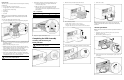
7. Following the diagram on the input terminal block cover:
a. Connect the input wires to the input terminal block
connections and ground.
b. Make sure that no loose strands remain and that the
terminal connection screws are tightened to torque
specifications found on the diagram immediately below the
terminal block.
Table 1: Input Wiring
(1) (2) (3)
208 V G L2 L1
230 V G N L
8. Replace the input terminal block cover.
Completing the UPS Assembly
Installing and Connecting the
Battery Modules
WARNING: To prevent personal injury, be sure that the battery
circuit breaker is in the off position.
1. Verify that the battery circuit breaker is off.
2. Slide the battery modules into the UPS chassis.
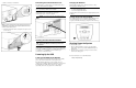
3. For each battery module:
a. Take out the connector cover screw (1).
b. Remove the connector cover (2) and discard.
c. Replace the connector cover screw to secure sheet metal.
4. Secure the batteries to the chassis with the screws provided.
5. Connect the cables.
NOTE: When attaching battery cable connectors, the connectors will
provide a positive latch into place if the release tabs are left free during
attachment.
Attaching the Bezels
NOTE: Leave the front bottom bezel off until wiring and UPS installation are
complete.
1. Attach the connector for the front panel to the electronics
module receptacles (1).
2. Lift the front top bezel into place (2).
3. Secure the bezel (1) to the chassis using the captive screws on
each side (2).