
UPS R6000 Models Installation Instructions


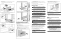


4. Turn on the battery circuit breaker.
NOTE: If optional extended runtime modules (ERMs) are attached, place
the ERM battery circuit breakers in the On position after the UPS circuit
breaker is placed in the On position.
5. Attach the front bottom bezel (1) using the two captive screws
on each side (2).
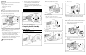
Connecting the Communications Port
The UPS includes a communications port that allows the unit to
exchange data with the host computer.
IMPORTANT: Power management software requires the communications
port to be appropriately cabled to the host computer.
Connect the UPS/computer interface cable (295245-004) from the
communications port on the UPS to the appropriate
communications port on the host computer.
CAUTION: Use only the specific cable supplied with the UPS to
connect the communications port to the host computer.
Installing Extended Runtime Modules
WARNING: To prevent personal injury or damage to the
equipment, the ERMs must be installed by a trained service
technician.
The ERM can be connected directly to an R6000 model or to
another ERM. Up to two ERM units can be connected. Depending
on the load, one ERM can extend the available UPS runtime by up
to 15 minutes. A second ERM can provide runtimes up to
30 minutes at recommended loads.
Powering Up the UPS
Turning on the Main Circuit Breaker
After a licensed electrician has the UPS properly wired to utility
power, turn on the AC mains at the service panel circuit.
The UPS automatically initiates a self-test. If the self-test is
completed successfully, the UPS enters Standby mode, designated
by the blinking green LED. If the self-test is not completed
successfully, refer to the user guide for more information.
Charging the Batteries
With the UPS in Standby mode, allow the batteries to charge
before putting the UPS into service.
IMPORTANT: The battery modules charge to:
• 90% of their capacity within 3 hours
• 100% of their capacity within 48 hours
Charge the batteries for at least 24 hours before supplying backup power to
the devices.
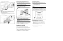
Placing the UPS in Operate Mode
Press and hold the On button (1) until the Utility LED turns solid
green, indicating that power is available at the UPS output
receptacles. The UPS acknowledges compliance with a short beep.
Shutting Down the System
To shut down the system:
1. Place the UPS in Standby mode by pressing the Standby
button. The load relays open and the Utility LED begins to
flash slowly.
2. Disconnect the AC mains by opening the switch or circuit
breaker at the utility panel.
For more information, refer to the HP website at
www.hp.com/products/ups