HP Remote Assistant User's Guide HP Part No.
Notice Notice The information contained in this document is subject to change without notice. Hewlett-Packard makes no warranty of any kind with regard to this material, including, but not limited to, the implied warranties of merchantability and fitness for a particular purpose. Hewlett-Packard shall not be liable for errors contained herein or for incidental or consequential damages in connection with the furnishing, performance, or use of this material.
License Agreement License Agreement Software License Agreement Please carefully read this license agreement before proceeding to open the media envelope. Rights in the software are offered only on the condition that the customer agrees to all terms and conditions of the license agreement. Proceeding to open the media envelope or install the software indicates your acceptance of these terms and conditions. If you do not agree to the license agreement, you may return the software for a refund.
License Agreement 5. Sub licensing and Distribution. Customer may not lease, sub license the software or distribute copies or adaptations of the software to the public in physical media or by telecommunication without the prior written consent of Hewlett-Packard. 6. Termination.
Regulatory Information Regulatory Information Notice for USA: FCC Statements This device complies with part 15 of the FCC Rules. Operation is subject to the following two conditions: (1) This device may not cause harmful interference, and (2) this device must accept any interference received, including interference that may cause undesired operation.
Regulatory Information FCC Regulations for Telephone Line Interconnection • This equipment complies with Part 68 of the FCC rules. On the outside surface of this equipment is a label that contains among other information, the FCC registration, the FCC registration number and ringer equivalence number (REN). If requested, this information must be provided to the telephone company. • This equipment uses the following Universal Service Code (USOC) jacks: RJ11C or RJ11W (single line).
Regulatory Information • This equipment cannot be used on telephone company-provided coin service. Connection to Party Line Service is subject to state tariffs. (Contact the state public utility commission, public service commission or corporation commission for information.) • If so required, this equipment is hearing-aid compatible.
Regulatory Information The Load Number (LN) assigned to each terminal device denotes the percentage of the total load to be connected to a telephone loop which is used by the device to prevent overloading. The termination on a loop may consist of any combination of devices subject only to the requirement that the total of the Load Numbers of all the devices does not exceed 100. The Load number for this product is 33.
Regulatory Information Declaration of Conformity DECLARATION OF CONFORMITY according to ISO/IEC Guide 22 and EN 45014 Manufacturer’s Name: Hewlett-Packard Company Hewlett-Packard Pte Ltd Manufacturer’s Address: 5301 Stevens Creek Blvd.
Limited Warranty Limited Warranty Software Warranty Software and Media: HP warrants for a period of ninety (90) days from the date of the purchase (a) the media is free from defects in materials and workmanship, and (b) that the software product will execute its programming instructions when properly installed. HP does not warrant that the operation of the software will be uninterrupted or error free.
Limited Warranty • Refer to the warranty statement provided with your HP computer for warranty limitations, customer responsibilities, and other terms and conditions. • The battery on board the HP Remote Assistant EISA Board is a customerreplaceable consumable and is not covered under this warranty.
Technical Support Technical Support Telephone Support The HP-supplied hardware and software in HP servers are covered by no-charge telephone assistance during the warranty period. In some geographic areas this telephone support is provided by Hewlett-Packard; in other areas, telephone support is provided by your reseller. For non-HP-supplied products, support numbers are included in the product documentation or are available from your reseller.
Technical Support Italian language (+31 20) 581-3338 Spanish language (+31 20) 581-3339 Other countries. For hardware service, contact your local HP office. For telephone support, contact your authorized HP reseller. Using Other Information Services Worldwide, access the HP NetServer World Wide Web home page: http://www.hp.com/go/netserver For software patches and driver updates: In the US, access the HP PC Support BBS: (408) 553-3500 Worldwide, access the HP FTP Server: ftp.netserver.hp.
Documentation Documentation HP Remote Assistant includes the following documentation: • This guide, which describes how to install and use HP Remote Assistant to manage network servers. It also provides installation instructions for HP Remote Assistant Communications Software (Terminal Plus) and pcANYWHERE32. • Application on-line help, which is available for the HP Remote Assistant Communications Software and pcANYWHERE32. • The HP Remote Assistant README.
Contents Quick Start ...............................................................................................................1 1 Introducing HP Remote Assistant........................................................................5 Package Contents .................................................................................................7 Who Should Use This Guide..................................................................................8 HP Remote Assistant Features and Functions ...
Contents Server Installation Overview................................................................................60 Using Pager Services ..........................................................................................60 Installing the DOS-Based HP Remote Assistant Server Software ........................61 Installing the NOS-Based HP Remote Assistant Server Software ........................63 Installing the Server Software for Novell NetWare ...........................................
Contents X. Disconnect ................................................................................................112 Using the SNMP Manager to Query HP Remote Assistant.................................113 Compiling the MIB Under OpenView..............................................................113 Defining a Query ...........................................................................................114 Viewing HP Remote Assistant Alarms With HP NSA .........................................
Contents Internal Peripheral Failure Codes...................................................................158 External Peripheral Failure Codes .................................................................161 I Keyboard Layouts..............................................................................................
Quick Start This chapter provides a quick overview of the steps required to set up and use HP Remote Assistant. If you have experience setting up computer hardware and software you can use the following section as a brief installation guide. The installation of the HP Remote Assistant accessory board requires the prior completion of system installation and configuration. It assumes that you have a bootable CD-ROM drive, and 8 MB of unallocated space on your hard disk for a Utility Partition.
Quick Start • From the HP NetServer Navigator CD-ROM, run the HP Remote Assistant Configuration Utility (select HP NetServer Utilities and move HP NetServer Utilities from the Navigator Main Menu). Set up: connection type (modem or direct), administrator access (required), event management, sensor and measurement thresholds, and paging notification. 2. Install server software (see Chapter 3 for detailed instructions): • Boot the HP NetServer Navigator CD-ROM.
Quick Start 4. Make your first remote connection (see Chapter 5 for detailed instructions): If you plan on using console redirection for your Windows NT 3.51 server, be sure that pcANYWHERE32 is already installed and configured as a host for your remote console. This should have been done when you installed pcANYWHERE32 (see Chapter 3). NOTE In the default installation, pcANYWHERE32 runs as a startup service on your server and is therefore always ready for a call from your remote console.
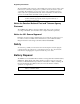
Quick Start 5. At the password prompt, enter the password that you specified in the HP Remote Assistant Configuration Utility. When the server accepts the password (and if no dial-back number was specified), the HP Remote Assistant Management Program starts up and displays its Main Menu: HP Remote Assistant Main Menu Server Name: HP NetServer Server ID: 001 1. 2. 3. 4. 5. 6. 7. 8. 9. X.
1 Introducing HP Remote Assistant HP Remote Assistant combines an intelligent EISA board and manager software to provide a powerful solution for remote server management, including monitoring and notification of server operations and events. HP Remote Assistant can be used independent of the Network Operating System (NOS) that is running on the server.
1 Introduction Figure 1-1. HP Remote Assistant Management Process HP Remote Assistant frees you from round-the-clock server monitoring. If HP Remote Assistant detects a problem that it cannot correct, it immediately notifies the assigned administrator by: • sending a page with a message that identifies the server and the nature of the problem • generating an SNMP alert (NetWare and Windows NT only) on a management console connected to the network.
1 Introduction Package Contents Your HP Remote Assistant product contains the following: • An HP Remote Assistant EISA circuit board, of one of the following models: ◊ Model D2967C (non-modem) ◊ Model D2968C (US/Canada/Mexico modem) Includes an on-board Hayescompatible modem capable of data transfer rates up to 14.4 kbps (V.32.bis). Technical specifications for the modem are provided in Appendix F. An RJ-11 telephone connection cable is packaged with model D2968C.
1 Introduction Who Should Use This Guide This guide is designed for people who are familiar with installing, managing, and troubleshooting servers on a network.
1 Introduction Remote Control An administrator at a remote console (connected to the server via a modem or dedicated serial cable) can view the server screen and take control of the keyboard— performing operations as if he or she were seated at the server. (HP Remote Assistant supports character-based server console screens and Windows NT graphics console redirection.) Remote server reset. An administrator at a remote console has virtual control of the server's power states.
1 Introduction Server Supervision Server Performance Monitoring. HP Remote Assistant monitors I/O performance by gathering statistics on EISA bus usage. An administrator at a remote console can also display a graphical representation of bus usage that is updated in real time, as well as a historical record of bus usage that indicates peaks and averages. Environment monitoring.
1 Introduction Upgradeable firmware. The HP Remote Assistant Management Program is stored in Flash ROM on the HP Remote Assistant board. If it is necessary to upgrade the firmware, a newer revision of the code may be downloaded to the programmable ROM. When available, new firmware versions can be obtained via the HP PC Bulletin Board System (BBS), on the FTP server, or from HP Support.
1 Introduction NOTE SCO UNIX does not support a bootable HP NetServer Navigator Utility Partition. Therefore you will have to create a separate bootable DOS partition in order to run the HP Diagnostic Assistant, EISA Configuration Utility, or the file transfer utility from a remote console. HP Remote Assistant includes SNMP Agents for the following network operating systems: • Novell NetWare v3.12, v4.1, and v4.1 SMP • Microsoft Windows NT Server 3.5 and 3.
2 Hardware Installation and Configuration This chapter provides instructions for installing the HP Remote Assistant EISA Board in a server and setting up a hardware connection that permits remote management of the server. (See Chapter 3 for information on installing HP Remote Assistant software.
2 Hardware Installation and Configuration Installing the HP Remote Assistant EISA Board Install the HP Remote Assistant EISA Board the same way that you install any other EISA board in your server. The exact procedure will depend on your particular server model. For specific information about installing EISA boards in your server, refer to the manuals that came with the server. See Appendix F, "Technical Specifications," for information about the power requirements for your HP Remote Assistant board.
2 Hardware Installation and Configuration Remove jumper block here Replace jumper block here Figure 2-1. Connecting the Power Control Cable in HP NetServer LM and LS Systems Remove jumper block here Replace jumper block here Figure 2-2.
2 Hardware Installation and Configuration Remove jumper block here Replace jumper block here Figure 2-3. Connecting the Power Control Cable in HP NetServer LC Systems Figure 2-4.
2 Hardware Installation and Configuration Figure 2-5. Connecting the Power Control Cable in HP NetServer LE Systems 3. Attach the "NetServer" end of the power control cable to the system. Refer to the figures below to determine how to connect and secure the power control cable in your HP NetServer system (LC, LE, LF, LH, LM, LS, or LX). In some cases you will need to remove the adhesive cover strip from one or more of the included cable clamps and tape the clamp to the system chassis.
2 Hardware Installation and Configuration Attach "NetServer" end of cable here Attach "Remote Assistant" end of cable here Tape clamps to chassis here HP Remote Assistant Board Figure 2-6.
2 Hardware Installation and Configuration Attach "NetServer" end of cable here Tape clamp under chassis here Attach "Remote Assistant" end of cable here HP Remote Assistant Board Figure 2-7. Installing the Cable in an HP NetServer LF or LH Attach "NetServer" end of cable here HP Remote Assistant Board Attach "Remote Assistant" end of cable here Tape clamp to chassis here Figure 2-8.
2 Hardware Installation and Configuration Attach "NetServer" end of cable here Attach "Remote Assistant" end of cable here HP Remote Assistant Board Figure 2-9. Installing the Cable in an HP NetServer LC Attach "NetServer" end of cable here Attach "Remote Assistant" end of cable here HP Remote Assistant Board Figure 2-10.
2 Hardware Installation and Configuration Verifying Board Installation You can verify that the Remote Assistant accessory board has been correctly installed by powering on the server and checking the board’s diagnostic LED at the rear of your system.
2 Hardware Installation and Configuration After the HP Remote Assistant EISA Board is installed and proper operation is verified, power on the server and run the EISA Configuration Utility as described in the next section. (Failure to run the EISA configuration utility may prevent the server from booting properly.
2 Hardware Installation and Configuration 2. From the Navigator's Main Menu, click Configuration Assistant. The utility displays three options: Express Custom Replicate 3. Click Custom and then select the NOS installed on your HP NetServer. Click Continue. 4. At the Custom Configuration menu, execute the EISA Configuration Utility. The system drops into DOS, loads a number of system and configuration files and presents you with the EISA Configuration Utility menu. 5. Five options are displayed.
2 Hardware Installation and Configuration At this point, you have two options depending on the way your system is set up. You can either boot from the CD-ROM drive, or you can boot from a bootable DOS partition on your hard disk. • Option 1, HP NetServer systems (LC, LH, LS, or LX) that have a CD-ROM drive. Disregard any on-screen instructions to remove the HP NetServer Navigator CD-ROM, and boot from the CD-ROM drive.
2 Hardware Installation and Configuration Setting Up the Remote Connection Once you've installed the HP Remote Assistant board, you can set up a remote connection that enables the server to communicate with a remote console. There are several options for setting up the server for remote connection. You can: • Connect to a remote console via the Remote Assistant's on-board modem (Models D2968C and D2969C).
2 Hardware Installation and Configuration Using the On-board Modem (Model D2968C) If your HP Remote Assistant board has an on-board modem, you can communicate with remote consoles by using the telephone cable to connect the modem port on the board to an RJ-11 telephone jack. At the remote console, there must also be a modem connection to complete the data link. The following figure illustrates the connection between the server and the remote console.
2 Hardware Installation and Configuration Using the On-board Modem (Int'l Modem Model D2969C) If you have the International Modem model of the HP Remote Assistant, the board has an on-board modem and a Line Access Module (LAM) to allow you to connect to your specific country's phone system. Connect the LAM to your HP Remote Assistant board and the country specific phone jack as shown below. A modem connection at the remote console is necessary to complete the data link.
2 Hardware Installation and Configuration Using an External Modem You can communicate with remote consoles by connecting an external modem via the board's serial communications port. A modem connection at the remote console is required to complete the data link. The following figure illustrates this type of connection joining the server and the remote console. Figure 2-14.
2 Hardware Installation and Configuration Using a Direct Serial Connection Instead of setting up modem communications, you can use a null modem cable to connect the server directly to a remote console through each computer's serial communications port. You can use this type of connection when you want to set up a remote console at the same site as the server. The figure below illustrates a direct connection between an HP Remote Assistant installed in a server and a stand-alone terminal.
2 Hardware Installation and Configuration Configuring a Null Modem Cable In a direct connection, the null modem cable has key signals crossed to make the terminal appear as if it were a modem. The figure below illustrates the cable configuration required for making a direct connection to the HP Remote Assistant.
2 Hardware Installation and Configuration Configuring the HP Remote Assistant After you've installed the HP Remote Assistant board and used the EISA Configuration Utility to set selected system parameters and have either installed or updated the Utility Partition, you are ready to proceed with the HP Remote Assistant Configuration Utility.
2 Hardware Installation and Configuration Starting the HP Remote Assistant Configuration Utility There are several ways to start the HP Remote Assistant Configuration Utility: From the HP NetServer Navigator Configuration Assistant, click Execute Card Utilities This option allows execution of utilities in addition to the Remote Assistant Configuration utility. OR From the HP NetServer Navigator's Main Menu, click NetServer Utilities, then click the Remote Assistant Configuration Utility button.
2 Hardware Installation and Configuration The Main Screen On startup, the Configuration Utility's main screen displays as follows: The Configuration Summary window behind the Main Menu window displays information that the Configuration Utility found after checking the board installation.
2 Hardware Installation and Configuration Configuring the HP Remote Assistant Board When you choose Configuration Menu from the Main Menu, the utility displays a menu that you can use to configure the HP Remote Assistant board for management operations, including: • Event management, including paging and server control • Setting sensor thresholds • Communications, including modem and direct serial connections • Remote terminal display type • Server identification • Support for console redirection using in
2 Hardware Installation and Configuration Configuring Event Management Choosing the Event Management command from the Main Menu displays the Event Management window where you can specify options to manage server events, and identify particular events that will generate a notification via pager. NOTE Some of HP Remote Assistant's Event Management parameters (excluding the shutdown string) can also be configured from a remote console.
2 Hardware Installation and Configuration If the cable is not connected, ASR can perform a hard reset, an action similar to pushing the reset button. Graceful shutdown will initiate the shutdown string sequence, but will not be able to turn the power off. See Chapter 2 for information on installing the cable provided with the HP Remote Assistant product. Restart on NOS Hang (ASR). When enabled, HP Remote Assistant initiates an Automatic Server Restart if the server NOS hangs.
2 Hardware Installation and Configuration Enabling Paging for Events The window also provides checkboxes for specifying events that will initiate a page to configured administrators. (All events are logged even if they are not enabled for paging.) NOTE HP Remote Assistant events can also generate alarms on an SNMP Management console. For more information on creating and viewing alarms, see Chapter 5.
2 Hardware Installation and Configuration Page on System Configuration or POST Error. When enabled, HP Remote Assistant sends a notification whenever it detects a system configuration error or a POST error at system boot time. Page on System Status Event. When enabled, HP Remote Assistant sends a notification whenever the status of the server changes. Events such as a corrected ECC single-bit error or a change to the server's configuration will cause notification.
2 Hardware Installation and Configuration When you configure HP Remote Assistant for the first time, you will find that the threshold fields display default threshold values. If you have previously changed any of these values, you can reset all threshold values to their factory default settings by pressing F4.
2 Hardware Installation and Configuration Configuring Communications For HP Remote Assistant to perform notifications and interact with administrators at remote consoles, you must configure it for communications by identifying the type of data link, and, in the case of modem communications, provide communications parameters for modem type and speed.
2 Hardware Installation and Configuration Select the appropriate button, and, if necessary, edit the modem initialization string. (For a complete listing of the on-board modem's AT commands, see Appendix C.) Press F4 to restore the factory defaults, or F10 to accept the settings and complete the communications configuration. External Modem To configure communications for an external modem, choose Communications from the Configuration menu.
2 Hardware Installation and Configuration To specify a modem, press F4. A list of modems supported for use with HP Remote Assistant is displayed. Select a modem from the scrollable list, then press Enter to return to the External Modem window. If the model of modem you are using does not appear in the modem list, you should select Generic Hayes-Compatible and see your modem documentation for an initialization string.
2 Hardware Installation and Configuration Table 3-1 Modem Commands for Remote Console Connection Feature enabled Command Result codes displayed Q0 Verbose result codes V1 Busy and dial tone detection X4 Auto answer S0=1 RTS/CTS (hardware) flow control &K3 DCD equals on-line state &C1 Disconnect on DTR On-to-Off &D2 Fixed DTE speed &Q5S36=7 Error correction &Q5 Select the appropriate baud rate from the scrollable list. If the modem supports data compression, (V.
2 Hardware Installation and Configuration page you or the server is set to dial you back during a remote connection). The baud rate defines the data transmission line speed between the serial port on your HP Remote Assistant and the serial port on the external modem (via a serial switch box or terminal server). Enter the initialization string and select the appropriate baud rate, then press F10 to complete the communications configuration.
2 Hardware Installation and Configuration Identifying the Server Choose the Server Identification command in the Configuration Menu to display the Server window in which you provide a server identifier name and identifier code. You can use the window to enter a server name and number that uniquely identifies the server to an administrator at the remote console. (For consistency, an administrator may want to use the NOS name of the server.
2 Hardware Installation and Configuration NOTE If the keyboard layout used by your server's operating system is not among the layouts currently supported by HP Remote Assistant, contact your local HP sales representative to see if a .KEY file has been developed for your keyboard (or select the layout that most closely matches your keyboard).
2 Hardware Installation and Configuration The ability to specify aliases allows an administrator to provide back-up administrators with access to the server through HP Remote Assistant. Remember that the software license authorizes a single administrator for each copy of HP Remote Assistant purchased. NOTE After configuration, an administrator can log in and reconfigure administrator data from a remote console by running the HP Remote Assistant Management Program.
2 Hardware Installation and Configuration Editing Administrator Aliases If this is the first time you are configuring administrator information, the Administrator window is empty. Add aliases by selecting a desired record and pressing Enter. (If you are using a mouse, you can also double-click a record in the window.) When a record is chosen, the Edit Administrator window appears, providing fields for entering and modifying administrator data.
2 Hardware Installation and Configuration NOTE TAP pagers require only a phone number for the service. There is no need to enter confirmation codes or commas. See the following section on TAP Paging. Some pager services may also require a pager ID, which must also be included in the Pager # string.
2 Hardware Installation and Configuration TAP Paging HP Remote Assistant can use your modem to transmit information about network events to your pager and/or alphanumeric receiving device. This information is typically sent via tower or satellite, or both. If your paging service supports the Telocator Alphanumeric Protocol (TAP), set pager status to TAP.
2 Hardware Installation and Configuration Pager ID The Pager ID or Personal Identification Number (PIN) is a number assigned to each pager. Many service providers use a numeric pager number as the Pager ID. Note that in the following example, the modem access number, also called the Pager Number (entered as described in the preceding panel) is distinct from the Pager ID.
2 Hardware Installation and Configuration To manage all of these variables and send messages dependably, you need to supply some basic information about your service provider and your pager. TAP Setup: Getting Started To set up HP Remote Assistant for Telocator Alphanumeric Protocol (TAP) paging you need to confirm with your service provider that their terminals can accept message lengths of 80 characters. You will also need: 1. A Pager ID, or Personal Identification Number (PIN) 2.
2 Hardware Installation and Configuration Troubleshooting Remote Assistant uses special log event codes for troubleshooting unsuccessfully sent TAP pages. Paging errors are codified so that they can be readily identified and should therefore assist you in diagnosing and correcting paging problems as they arise. If you need further assistance relative to paging problems, contact either your paging service or Hewlett-Packard Technical Support. Select Show Event Log to view log events.
2 Hardware Installation and Configuration Press Enter to send the test page to administrator aliases in the list. When the paging is complete, the Configuration Utility displays a dialog box informing you that the page was sent. If the page is not received, try editing the Pager# string in the Edit Administrator window to change the number of pauses that specify the connection delay. If you are using a TAP pager, check the service phone number, the pager ID and the password.
2 Hardware Installation and Configuration Testing the Temperature Sensor The Diagnostics Menu provides a Test Temperature Sensor command that you can use to verify that the temperature sensor on board the HP Remote Assistant board is operational. To test the temperature sensor, choose Test Temperature Sensor from the Test Features Menu. If the sensor is detecting temperature, HP Remote Assistant displays a dialog box informing you that the on-board temperature sensor has passed the test.
2 Hardware Installation and Configuration • A code that provides specific data about the event (usually a measured value of the event—see Appendix A) To save the current log as an ASCII file, press F5 (or click Save to File). A dialog box appears, asking you to type a DOS path and filename for the file. Type the filename and press Enter. The utility saves the file under the specified filename. Afterwards, you can use any text editor to open the file and reformat it for viewing and printing.
2 Hardware Installation and Configuration When running the HP Remote Assistant Management Program from a remote console an administrator can view more detailed information about bus utilization, including a real-time graphical representation of bus usage and a historical graph showing recent activity patterns. For more information, see Chapter 5.
3 Server Software Installation and Configuration This chapter describes how to set up your server using the HP Remote Assistant software for remote server management. Installing the server software is the first half of the installation process, and involves three steps: 1. Installing the DOS-based HP Remote Assistant server software 2. Installing the NOS-based HP Remote Assistant server software 3. Configuring the SNMP Agent to send traps to your console.
3 Server Software Installation and Configuration Server Installation Overview HP NetServers in a remote management system require access to a HP NetServer Navigator Utility Partition, or to 8 MB of disk space available in a bootable DOS partition installed on the hard disk. Also check to be sure you have 200 KB (maximum) of disk space available on the NOS partition for agents and drivers. And if you plan to install pcANYWHERE32 (Windows NT 3.
3 Server Software Installation and Configuration Installing the DOS-Based HP Remote Assistant Server Software In order to remotely run DOS utilities and perform DOS file transfers, you must install the HP Remote Assistant software on the server. NOTE If you previously installed a NetServer Navigator Utility Partition, you can skip the procedures described in this section. The DOS based Remote Assistant server software is automatically installed by the Navigator.
3 Server Software Installation and Configuration so, you need an EISA Configuration Utility disk (created from the HP NetServer Navigator CD-ROM) or the HP NetServer #1 Disk—provided with older HP NetServers. When the utility and its associated files are copied to the hard disk, the Installer automatically creates the directory C:\CF in which to store it.
3 Server Software Installation and Configuration Installing the NOS-Based HP Remote Assistant Server Software To complete the server side of the installation, you must do one or more of the following depending upon the network operating system of the server(s) you want to manage: For Novell NetWare Servers, proceed to the "Installing the Server Software for Novell NetWare" section of this chapter.
3 Server Software Installation and Configuration Installing the Server Software for Novell NetWare For Novell NetWare, the additional HP Remote Assistant software you install on each NetWare server is listed below. Note that during installation of the NSA management console software you may choose to install these NLMs on all or selected NetWare servers.
3 Server Software Installation and Configuration Setting Up the SNMP Agent for NetWare The SNMP Agent NLM (HPRAGENT.NLM) file provided on your HP Remote Assistant Server Diskette permits SNMP-based network access of HP Remote Assistant information and alarms for servers running Novell NetWare. This section provides instructions for installing, loading, and configuring the Agent. Installing the SNMP Agent This installation procedure assumes that a Novell NetWare server has already been set up correctly.
3 Server Software Installation and Configuration Setting Up a Community The HP Remote Assistant SNMP Agent requires that the NetWare Agent NLM (SNMP.NLM) already be loaded. If it is not loaded before HPRAGENT, it will be loaded automatically without optional parameters. To add options that set up a community, you must load SNMP.NLM before HPRAGENT.
3 Server Software Installation and Configuration The syntax for the options is as follows: M[onitorCommunity] [= [communityName] ] C[ontrolCommunity] [= [communityName] ] T[trapCommunity] [= [communityName] ] The option parameters (such as MonitorCommunity) are not case sensitive. In addition, when specifying option parameters, you need enter only the first character of the option name, although complete or partial names are also accepted.
3 Server Software Installation and Configuration Examples To set the read/write community name to secret, enter the following command: LOAD SNMP ControlCommunity=secret To disable all read/write access, enter the following command: LOAD SNMP ControlCommunity To allow any community name to be used for read access, enter the following command: LOAD SNMP MonitorCommunity= To allow any community name read-only access and to set the read/write community name to private, enter the following command (note the abb
3 Server Software Installation and Configuration ASR Program Files and Parameters for NetWare The file HPASR.NLM provides ASR capabilities for a server running NetWare. Loading this NLM on a server enables ASR; unloading it disables ASR (without causing the system to restart itself). The default time after which the server will restart after a crash or hang is 10 minutes.
3 Server Software Installation and Configuration Installing the Server Software for Microsoft Windows NT For Microsoft Windows NT, the additional HP Remote Assistant software you install on each Microsoft Windows NT server includes: • HP Remote Assistant SNMP Agent This agent works behind the scenes to handle all SNMP queries from the remote management console and sends SNMP traps to the remote management console.
3 Server Software Installation and Configuration Setting Up the SNMP Agent, ASR, and Console Redirection for Windows NT To use the HP Remote Assistant agents and ASR service, you must have already set up your Windows NT server with TCP/IP and SNMP Services. NOTE TCP/IP and SNMP Services are available with the standard Windows NT product. Make sure that you've set up SNMP services through the Windows Control Panel: Network application.
3 Server Software Installation and Configuration 6. If you want to be able redirect what's graphically displayed on your server to a remote Windows NT 3.51 or Windows 95 PC console, you must also install the pcANYWHERE32 host software included with this package. To install pcANYWHERE32: a. Insert the pcANYWHERE32 Disk 1 into drive A and, at the DOS command prompt, type: a:\setup Follow the instructions on the screen. b.
3 Server Software Installation and Configuration pcANYWHERE32 menu bar pcANYWHERE32 action button bar e. At the main program window, click the Be A Host PC button. Select the Modem connection item (see illustration below). Right mouse-click on the Modem connection item to get the connect item drop-down menu.
3 Server Software Installation and Configuration f. Choose "Properties…" from the drop-down menu and in the "Connection Info" section, verify that the COM port and modem type are set correctly. When finished, click the "OK" button to return to pcANYWHERE32's main program window. g. Now, run the Modem connection item by double-clicking it. This initializes the modem and establishes the Modem connection item you just set up as the default.
3 Server Software Installation and Configuration • ASRSRVC.EXE This ASR service program resets the ASR hardware via calls to the ASR driver. The polling period is 30 seconds by default. It may be reconfigured by the user via the ASRUSER program. • ASRUSER.EXE This program runs from an NT DOS command prompt. It is used to load the ASR service program, change time-out parameters, and get ASR statistics. It accepts the following command line options: /g Loads the ASRSRVC service program and then starts it.
3 Server Software Installation and Configuration Installing the Server Software for OS/2 For IBM OS/2, the additional HP Remote Assistant software you install on each IBM OS/2 server includes: • HP Automatic Server Restart Automatic Server Restart (ASR) eases the burden of dealing with a system crash or hang by automatically restarting the system if such a failure occurs. A combination of software and hardware is used to do this.
3 Server Software Installation and Configuration 3. Edit your CONFIG.SYS file to include the following lines: DEVICE=C:\HPNSA\HPASR.SYS RUN=C:\HPNSA\ASRSET.EXE/ENABLE Configuring ASR for OS/2 When the ASR driver loads it is not enabled. Adding the RUN command to CONFIG.SYS (described above) enables ASR. You can also change the default ASR parameters in CONFIG.SYS. For example, you could enable ASR and set the ASR time-out to five minutes by adding the following line to CONFIG.SYS: RUN=C:\HPNSA\ASRSET.
3 Server Software Installation and Configuration Installing the Server Software for SCO UNIX For SCO UNIX, the additional HP Remote Assistant software you install on each SCO UNIX server includes: • HP Automatic Server Restart Automatic Server Restart (ASR) eases the burden of dealing with a system crash or hang by automatically restarting the system if such a failure occurs. A combination of software and hardware is used to do this.
3 Server Software Installation and Configuration Perform the following steps to install ASR for SCO UNIX: 1. Run the custom installation program, custom, from the command line. 2. Select the Install option. 3. Select A New Product from the list of products. 4. Select Entire Product from the options list. 5. Insert the disk labeled HP Remote Assistant SCO UNIX ASR Driver Diskette in the default floppy drive. 6. Select the HP NetServer ASR Package. 7.
3 Server Software Installation and Configuration ASR Program Files and Parameters for SCO UNIX The following program files provide ASR for SCO UNIX: • /dev/asr. The ASR driver. It provides the low-level interface to the ASR hardware. • /etc/asrdaemon. This program is a daemon that calls the driver to start and stop the ASR timer. It also creates the process that notifies the ASR hardware that the OS is still active (not hung). The ASR driver must be installed before the daemon can be run.
3 Server Software Installation and Configuration Configuring the SNMP Agent to Send Traps to Your Console Once the SNMP Agent is loaded, it will generate SNMP traps for the event codes that default to ON in the table below (see Appendix A for event code descriptions). These traps may be received by any management platform that supports SNMP, including HP OpenView and Novell NMS.
4 Setting Up the Remote Console This chapter describes how to set up a remote console to communicate with the HP Remote Assistant accessory in your server.
4 Setting Up the Remote Console Remote Console Installation Overview For best results at the remote console, use an ANSI color terminal that supports 25line mode and IBM PC character set, the configuration supported by the HP Remote Assistant Communications Software (Terminal Plus). Terminal Plus requires a 386-based (or faster) PC, running Windows 3.1, 3.11, Windows 95, or Windows NT 3.5x, with at least 12 MB of available hard disk space, depending upon the terminal emulation program you choose.
4 Setting Up the Remote Console The Remote Assistant installation program copies the application to the remote console's hard disk and then runs the Terminal Plus Setup program. You are prompted for information regarding the communications port to which your modem is connected and must specify a modem type and modem speed. (See Appendix B for a list of recommended modems.) The following figure illustrates Terminal Plus as it appears in a Windows Program Manager window.
4 Setting Up the Remote Console Follow the on-screen instructions to complete installation of pcANYWHERE32. 3. After pcANYWHERE32 is installed, restart Windows NT or 95. To run pcANYWHERE32, double-click the pcANYWHERE32 program icon in the pcANYWHERE32 program group, or select it from the Start menu. 4. The first time you start pcANYWHERE32, the Smart Setup Wizard helps you configure your system by prompting you for basic information such as COM port and modem specifications. 5.
4 Setting Up the Remote Console 4. Click "Details..." to verify that the correct COM port and modem type are properly set. 5. Click the Settings tab and enter the server's phone number. 6. Click the OK button to return to the main program window. 7. If you wish to rename the connection item to something other than "CHTEMPL," right-click the connection item and then click Rename. Type in the new name. 8. You can copy and paste this icon multiple times to create an icon for each server you manage.
4 Setting Up the Remote Console Table 4-1. Terminal Emulation Settings Setting Recommended Alternate Emulation ANSI Color Monochrome ANSI/VT-100 Character Set Extended PC/IBM PC ANSI Screen Dimensions 80 x 25 80 x 24 Line Wrap OFF Local Echo OFF Scroll ON Carriage Return Translation None Backspace Translation None Cursor Underline, blinking Table 4-2.
4 Setting Up the Remote Console NOTE In addition to the special keys emulated with ANSI escape sequences, HP Remote Assistant only accepts the 128 standard U.S. ASCII character (7-bit) codes. Extended character set characters are NOT accepted by HP Remote Assistant. For more information on keyboard considerations, see Appendix I.
4 Setting Up the Remote Console Connecting to HP Remote Assistant from an HP NSA Management Console HP NetServer Assistant (NSA) is a server management application used with HP OpenView that comes standard with most HP NetServer systems. It allows you to manage all your servers from a single console (local or remote).
4 Setting Up the Remote Console 7. In the Parameters entry area, type the command line that will pass server names set in HP NetServer Assistant on to HP Remote Assistant: infonums.dcd %server% The HP NetServer Assistant server name will be sent to the HP Remote Assistant dialer so that launching HP Remote Assistant as a tool will automatically connect you to the dialer entry that matches the server name.
4 Setting Up the Remote Console Running Terminal Plus from HP NetServer Assistant After Terminal Plus has been installed on the computer that will serve as the remote console and HP Remote Assistant has been defined as an HP NetServer Assistant tool, you can start Terminal Plus directly from HP NetServer Assistant. To start Terminal Plus from HP NetServer Assistant: 1. Start HP OpenView for Windows from the HP OpenView Program group.
5 Using HP Remote Assistant to Manage Server Operations Once Terminal Plus for Windows is running on the console, a qualified administrator (configured in the HP Remote Assistant Configuration Utility) can log into the server and begin using HP Remote Assistant to manage server operations. The HP Remote Assistant initiates remote console redirection via the Terminal Plus program (included in the package).
5 Using HPRA to Manage Server Operations 2. Once connected, press Enter several times to display the Login Name prompt. 3. At the Login Name prompt, enter the administrator name you configured using the HP Remote Assistant Configuration Utility. For more information on configuring administrator names, see the section, "Configuring Administrator Names," in Chapter 2. 4. At the password prompt, enter the password you assigned using the HP Remote Assistant Configuration Utility.
5 Using HPRA to Manage Server Operations Remote Assistant Server Management Program Options When the HP Remote Assistant Management Program's Main Menu is displayed you may choose management operations from application menus by typing an item number and pressing Enter. (You can also configure Terminal Plus to select options by clicking an option number with your mouse.
5 Using HPRA to Manage Server Operations NOTE If the message "ALERT PENDING" appears in the Main Menu, it means that an event has occurred for which HP Remote Assistant has not yet sent a notification because the modem is occupied by the remote connection. However, the event will appear in the log of events. (See the section below for more information on viewing the log.) If an administrator disconnects without reading the log, HP Remote Assistant will immediately send a page about the event.
5 Using HPRA to Manage Server Operations To view the contents of the last screen saved upon an ASR event, type D and press Enter. HP Remote Assistant displays the last screen displayed before restart. If the saved screen was in 25-line mode, the entire server screen is displayed, unless the terminal is in 24-line mode, in which case line 24 is not displayed. If the captured screen was in 50-line mode, the screen scrolls to reveal the entire screen (Terminal Plus provides scroll bars).
5 Using HPRA to Manage Server Operations The status information includes the server's identifying name and code, the current version of the HP Remote Assistant firmware, current voltage readings (the +3.3V level only appears if it is relevant for the system being monitored), and the current temperature level. (If the server is shut off, a message will appear instead, indicating that the server is powered down.
5 Using HPRA to Manage Server Operations 3. Console Redirection An important feature of remote server management is the ability to take control of the server from the remote console. When you choose Console Redirection from the Main Menu, HP Remote Assistant displays these options: Text Console Redirection NT Graphics Console Redirection.
5 Using HPRA to Manage Server Operations When you want to relinquish control of the server and return to the HP Remote Assistant Management Program, press Ctrl-B. (If you are using Terminal Plus for terminal emulation, a "soft key" labeled "Quit Redirection" is available for quitting console redirection.) Switching to Text Mode in OS/2 If your server is running IBM OS/2, you can create a hot key to invoke an OS/2 full screen session.
5 Using HPRA to Manage Server Operations 16. Close the Desktop Settings menu. After creating hot key in OS/2, you can "press" the hot key by sending a series of keystroke combinations from the remote console. To invoke an OS/2 Full Screen session from the remote console, type the following keystroke combinations: Local Remote 1. Alt Esc Ctrl-A Esc Esc 2. Ctrl Esc Ctrl-D Esc Esc 3. Home Esc [ H 4. Enter Enter 5. Ctrl-\ Ctrl-D \ 6. Shift F10 Ctrl-F a Ctrl-F 0 7.
5 Using HPRA to Manage Server Operations Select NT Graphics Console Redirection. The display responds with: Going into NT Redirection mode... Control of the modem port is released for use by pcANYWHERE32 and the server is set to await your call back. Follow the on-screen instructions. EXIT Terminal Plus and call back the server using pcANYWHERE32. Disregard the NO CARRIER message. NOTE The remote server waits up to five minutes for the console to connect and take control.
5 Using HPRA to Manage Server Operations The option you choose depends on the problems experienced by the system. NOTE Power Cycle and Power Down are only available on HP NetServer systems that accept the power control cable from the HP Remote Assistant board. For more information on setting up the power control connection, see Chapter 2. Selecting option 1, 2, or 3 also causes the redirection of the server console to the remote console from which you are running HP Remote Assistant.
5 Using HPRA to Manage Server Operations NOTE If you have a Utility Partition installed on the server, you can transfer files directly to it via Console Redirection. Select Remote File Transfer from the HP Remote Assistant Utilities menu on the Utility Partition. See "Sending Files" and "Receiving Files" below for details on how to transfer files. HP Remote Assistant supports the ZModem and XModem file transfer protocols.
5 Using HPRA to Manage Server Operations 6. Run Server Utilities HP Remote Assistant automates the task of launching and running previously installed DOS utilities from the remote console. This feature is especially useful for administrators who need to perform diagnostics or a configuration from a remote location. When you choose Run Server Utilities from the Main Menu, HP Remote Assistant displays a menu of utility launch options. 1. 2. 3. 4.
5 Using HPRA to Manage Server Operations If you have installed the Remote Assistant software to a DOS partition on your HP NetServer's hard disk you can add Diagnostic Assistant files as follows: 1. Retrieve the HP NetServer Diagnostic Assistant Diskette from the pouch located inside the HP NetServer cabinet. If your HP NetServer does not have the diskette, you can download the diskette image from the HPPC Support BBS by connecting to (408) 553-3500.
5 Using HPRA to Manage Server Operations NOTE You may also need to update the EISA Configuration Utility files on the Utility Partition if a new version is required for the new BIOS. For example, to send new BIOS files to the server from the NetServer Navigator CD: 1. Insert the Navigator CD in the remote console’s CD-ROM drive (e.g. drive E). 2. From Terminal Plus, select Send Binary File. 3. From the Transfers menu bar, enter the directory: e:\lx\bios 4. Include all files in the transfer by entering *.
5 Using HPRA to Manage Server Operations HP Remote Assistant maintains a log of bus activity for the preceding seven days (if the HP Remote Assistant has not been shut down during that period). You can page through the last seven days by typing P or N, and pressing Enter. You can display a table for the entire seven-day period by typing D and pressing Enter.
5 Using HPRA to Manage Server Operations NOTE If the HP Remote Assistant SNMP is loaded, server events can also generate SNMP traps. (Settings in the Event Management Menu do not control the generation of alarms.) For more information on configuring traps, see the section, "Viewing HP Remote Assistant Alarms with HP NetServer Assistant," later in this chapter. Page on Voltage Threshold.
5 Using HPRA to Manage Server Operations Page on System Configuration or POST Error. When enabled, HP Remote Assistant sends a notification whenever it detects a system configuration error (for example, a board has been installed without configuring it through the EISA Configuration Utility), or a POST error. System configuration and POST error events are those listed in Appendix A with the format 7xxx. Page on System Status Event.
5 Using HPRA to Manage Server Operations NOTE Passwords are displayed as eight asterisks and so are not visible on-screen. The menu provides three commands for modifying administrator data: (C)hange, (D)elete, and (T)oggle Pager. When you press M to return to the HP Remote Assistant Main Menu, a prompt appears asking if you want to save any changes you made to the user information.
5 Using HPRA to Manage Server Operations X. Disconnect When a remote management session is over, you can end the communications session with the server by choosing Disconnect from the HP Remote Assistant Main Menu. It is important that you disconnect when your tasks are complete, otherwise the modem will remain tied up for the terminal session and the HP Remote Assistant board will be unable to alert administrators of any server problems.
5 Using HPRA to Manage Server Operations Using the SNMP Manager to Query HP Remote Assistant Installation of the HP Remote Assistant SNMP Agent and MIB permits compiling and querying of the MIB under any management platform that supports SNMP, including HP OpenView and Novell NMS. When compiled, the MIB tells the SNMP Manager which HP Remote Assistant device variables are available for querying or setting.
5 Using HPRA to Manage Server Operations NOTE If you are using an SNMP management platform running on a UNIX platform, you can use FTP in ASCII mode to transfer the MIB to your workstation. Defining a Query OpenView allows you to generate tables or graphs showing information available in HP Remote Assistant's MIB database. To define a query, you select the server on which an HP Remote Assistant EISA Board is installed, then select the variables that you want to query. 1.
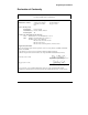
5 Using HPRA to Manage Server Operations Selecting Variables to Query The accessible SNMP variables are listed in the Variables box. The variables are displayed in a tree fashion with the MIB-II level displayed as a default. To display the HP Remote Assistant variables, you need to navigate through the tree by clicking the Up and Down buttons. The graphic below indicates a sample tree structure through which you would navigate to the HP Remote Assistant variables.
5 Using HPRA to Manage Server Operations iso org dod internet directory mgmt experimental private enterprises mib-2 hp system interfaces ...
5 Using HPRA to Manage Server Operations Individual values (columns) may be selected for an SNMP table by clicking on the Down button to move down the tree below the table and entry definitions to the individual column variables. You may select multiple column table variables and then click on Add to add these to the query. In this case, any previously selected variables are removed from the selection list, as only columns within a single table may be queried.
5 Using HPRA to Manage Server Operations Performing a Query After you enter the appropriate information for the device, variable, and options, click on Perform to execute the query. If a polling value other than zero was set, the table or graph will be updated periodically. When a table of data is displayed, you can use the buttons provided in the window to poll the device, set a variable, copy selected cells to the clipboard, or save the displayed data to a log file.
5 Using HPRA to Manage Server Operations Displaying Alarms After the alarm icons have been created from HP Remote Assistant agents, you can display the trap agent alarms available on a particular server by double-clicking the server icon from the HP OpenView map. Here is an example of the type of subobject alarms created from HP Remote Assistant traps: The alarm icons change color to indicate status. Double-clicking an alarm subobject displays its associated alarm log.
6 Troubleshooting This chapter provides some guidelines for troubleshooting HP Remote Assistant. Problems With Installation My server does not have a power control adapter to which I can connect the power control cable. You can not use HP Remote Assistant's server power-cycle and graceful shutdown features. ASR drivers were already loaded on my server when it was configured for HP NetServer Assistant.
6 Troubleshooting The HP Remote Assistant EISA Board does not respond to the HP Remote Assistant Configuration Utility. Make sure that the HP Remote Assistant EISA Board is securely seated in an EISA slot. Check the LED on the back panel of the board. If it is not alternately flashing green and yellow lights, something is wrong with the board, see Appendix H, "LED Codes," for more detail. External Modem The external modem is not responding to HP Remote Assistant.
6 Troubleshooting Has a pager number and paging string been set up in HP Remote Assistant Configuration Utility? Also check if the telephone cord is properly connected to the back of the HP Remote Assistant EISA Board (or an external modem if you are using one). If you are using an external modem, verify that the correct cable is properly connected. If your pager service generates repetitive tones when it answers, the HP Remote Assistant modem may interpret the tones as a busy signal and attempt to re-dial.
6 Troubleshooting 2. Your paging service provider is not completely adhering to the alphanumeric paging protocols. If this appears to be the case, call HP Technical Support. 3. It is also possible that you are not dialing the correct modem access number. Check to see if the number you are dialing responds with typical modem handshaking protocols. If not, call your pager service provider and double-check to be sure you are dialing the correct modem access number (Terminal Number).
6 Troubleshooting I seem to be missing a line of text when using console redirection. This is to be expected when the HP Remote Assistant terminal settings are configured for 24-line display. If possible use a terminal emulator (like Terminal Plus) that supports 25-line mode. During console redirection my screen gets out of synch. This can happen when HP Remote Assistant is configured for 25-line mode but the terminal emulator only supports 24 lines.
6 Troubleshooting DOS File Transfer When I attempt to send a file to the server, I get the message "Timed out waiting for the file transfer utility to start." Files cannot be transferred between the server and the remote console unless the file transfer utility (HPRAXFER.EXE) has been successfully launched. Check that the server is running in DOS mode and that the file transfer utility is in the current directory or in the DOS path.
A Event Codes The table below describes the event codes that can be sent via pager or listed in the event log. When HP Remote Assistant sends a page about a server event, it includes the server identifying number and a four-digit code identifying the event. It's a good idea to copy appropriate sections of this table and keep it with the pager you use to receive notifications.
A Event Codes Code Log Page Description Data Measured 0501 x x Warning NOS hang (ASR) Timeout (secs) 0502 x x Server Restarted after NOS hang (ASR) Timeout (secs) 0503 x ASR Timer Enabled Time out (secs) 0504 x ASR Timer Disabled 0601 x Remote Initiated 0602 x Remote Initiated Reset or Power Cycle 0603 x Remote Initiated Power Down 0701 x Server BIOS Initialization 0800 x x Bus Utilization Threshold Warning 0900 x x Test Page 0901 x TAP No connect,
A Event Codes Code Log Page Description Data Measured 9005 x x IO Channel Check Slot # 9006 x x Software NMI 9009 x x PCI Parity error 9010 x x PCI System error 9011 x x CPU Failure during POST 9012 x x EISA Failsafe Timeout 9016 x x System Error Limit Exceeded (Fatal) 9021 x x PCI System error 9034 x x ECC Multi-bit error Bus ID Bus ID NOTE Notification and log messages are limited to a length of 40 characters or less.
B Recommended Modems The following chart lists modems recommended by HP for use with PCs serving as remote consoles in an HP Remote Assistant server management solution. If you are using an external modem at the server, HP recommends that you use the same model (or at least the same brand) of modem at the remote console.
C Modem Commands This appendix provides a table of AT commands and S-Registers for the modem on board the HP Remote Assistant EISA Board (Models D2968C and D2969C only). These commands and S-Registers do not apply to Model D2967 which utilizes an external modem. The complete text of the modem manual can also be found on the HP Support Assistant disk.
C Modem Commands Command Values &BSn n = 0 or 1 Def Description &BS0 means maximum transmit block size of 64 characters. &BS1 means maximum transmit block size of 256 characters. *** $BAn n = 0 or 1 *** $BA0 means Baud Adjust is off, speed conversion is on. $BA1 means Baud Adjust is on, speed conversion is off. &Cn n = 0, 1, 2, or 4 &C0 forces Carrier Detect on. *** &C1 lets Carrier Detect act normally. &C2 lets Carrier Detect drop S24 time on disconnect.
C Modem Commands Command Values Def Description $EBn n = 0 or 1 *** $EB0 enables 10 bit mode. %En n=0 thru 5 $EB1 enables 11 bit mode. % E0 = Modem Won’t Escape. *** % E1 = +++ Method (default setting). % E2 = Break Method. % E3 = Either +++ or Break Method. % E4 = No "OK" Response to +++ % E5 = "OK" Response to +++ #Fn n = 0 or 1 #F0 means no fallback when on-line. #F1 means fallback from 14400 to 4800 bps when on-line. *** &F n= 0, 8 or 9 #F2 means fallback to 4800 bps from 14.
C Modem Commands Command Values Def L7 lists additional parameters. L7 #Ln Description n = 0 thru 3 *** #L0 means modems negotiate V.42 Mode. #L1 means MNP on and LAP-M off. #L2 means LAP-M on and MNP off. #L3 means no detection phase but go directly to LAP-M. Mn n = 0 thru 3 M0 means Monitor speaker always Off. *** M1 means Monitor speaker On until carrier detected. M2 means Monitor speaker always On. M3 Monitor speaker on during dialing/off during handshaking. $MBn $MB75 selects CCITT V.
C Modem Commands Command Values Def Description &Rn n = 0, 1 or 2 *** &R0 lets Clear to Send act normally. &R1 forces Clear to Send on. &R2 drops for 1 second on disconnect. $Rn n = 0 or 1 *** $R0 means disconnect after 12 retransmits. $R1 means do not disconnect after 12 retransmits. &RFn n = 0 or 1 &RF0 selects CTS follows RTS. *** &RF1 selects CTS to act independently. Sr=n r = 0-34 Sets value of Register “r” to value of “n”, where “n” is entered in Decimal format.
C Modem Commands Command Values #Tn n = 0 or 1 Un n = 0, 1, 2, or 3 Def Description #T0 turns off Trellis Coded Modulation. *** #T1 turns on Trellis Coded Modulation. U0 places modem in Analog Loop Originate Mode. U1 places modem in Analog Loop Answer Mode. U2 places modem in Remote Digital Loopback test mode. U3 places modem in Local Digital Loopback test mode. Vn $VDn n = 0 or 1 n = 0 or 1 V0 means Result Codes sent as digits (terse response).
C Modem Commands Command Values Def Description ! in Dial command Causes modem to Flash On-Hook. (Not applicable with pulse dial in Austria and Germany. Not applicable in the U.K.) @ in Dial command Causes modem to wait for ringback, then 5 seconds of silence before processing next part of command. +++AT Escape Code. Puts modem in Command Mode while still remaining On-Line. Enter +++ followed by the letters A and T, up to ten command characters, and a RETURN.
C Modem Commands S-Register Unit Range Default Description S11 1 mSec 80-255 80 Sets time duration of and spacing between tones in tone-dialing. S13 ASCII 0-127 37 Defines Remote Configuration Escape Character. S17 10 mSec 0-2.5 250 mSec Defines length of break time (space) to PC. S24 50 mSec 0-255 20 Sets DSR/CTS/CD dropout time. Default (20) equals one second. S25 100 mSec 0-255 0 Sets DTR dropout time. 0 default equals 50 mSec.
C Modem Commands Digit (Terse) Words (Verbose) Effect 11 CONNECT 4800 Modem has detected carrier at 4800 bps and gone on-line. 12 CONNECT 9600 Modem has detected carrier at 9600 bps and gone on-line. 13 CONNECT 14400 Modem has detected carrier at 14400 bps and gone on-line.
D Keyboard Mapping When keyboard commands are redirected to the server keyboard from a remote console, keystrokes on a generic terminal emulation keyboard may not control all PC keyboard keys. Because there is no direct mapping between a generic terminal keyboard and a PC's keyboard, most special keys on the PC keyboard must be emulated using character strings.
E Graceful Shutdown Keystroke Syntax General Guidelines If HP Remote Assistant's graceful shutdown feature is enabled, an administrator can use the HP Remote Assistant Configuration Utility to specify a keystroke sequence that HP Remote Assistant uses to perform a graceful shutdown. HP Remote Assistant provides a syntax for entering complex keystrokes.
E Graceful Shutdown Keystroke Syntax Examples This section provides example shutdown strings for some network operating systems. You may need to modify the strings for your implementation of a NOS. NetWare Shutdown String {CTRL-ESC}{ENTER}{1}{ENTER}DOWN{ENTER}{60}EXIT{ENTER} Windows NT Shutdown String The following example assumes that the console is not locked. {CTRL-ALT-DEL}{1}s{ENTER}{10} SCO UNIX Shutdown String This following example assumes permission to execute a shutdown.
E Graceful Shutdown Keystroke Syntax Keystroke Codes The following table identifies the keystroke codes for entering non-printable characters in a graceful shutdown string.
F Technical Specifications This appendix provides specifications for the HP Remote Assistant EISA Board. Feature Description On-Board Features 32-bit EISA Bus Master board (occupies a single slot) External 9-pin RS232 connector Rear panel power-down reset switch 80C186 12.5 MHz, 16-bit microprocessor 256 KB 85ns Static RAM memory 256 KB of Flash ROM memory (firmware is customer-upgradeable) 8 KB of nonvolatile (EEPROM) memory Physical Characteristics Board dimensions: 34 cm long x 11.5 cm wide x 1.
F Technical Specifications Feature Description On-Board Modem Compatibility Hayes Generic (AT-compatible) (D2986B and Data Mode Protocols 14400/12000 bps (V.32bis). D2969C) 9600/4800 bps (V.32).2400 bps (V.22bis). 1200 bps (Bell 212A), 300 bps (Bell 103) Error Correction V.
G Battery Operation The HP Remote Assistant EISA Board includes an on-board Nickel Cadmium (NiCad) battery pack that ensures a supply of power to the board components, including the onboard modem in Models D2968C and D2969C. This battery pack contains five cells and is rated at 6.0V at 1100mAH. In case of a cutoff of AC power to the server, or a power supply failure, the battery can continue to power the HP Remote Assistant for up to one hour.
G Battery Operation Battery Operation If the server's power is interrupted, HP Remote Assistant automatically switches to battery operation. HP Remote Assistant logs the event and generates a pager alert (if configured). In addition, some HP Remote Assistant functions that require the server to be powered up are also suspended, including console redirection, EISA Bus Utilization monitoring, and server resets.
G Battery Operation Life Expectancy The life expectancy of the battery pack varies depending on temperature extremes and number of power cycles experienced by the cells. A nominal life expectancy will be over two years. If the battery pack requires more than one hour to fully charge, or if the board provides less than one hour of operation while operating on battery power, it may be time to replace the battery pack.
H LED Codes These tables list the error codes which will be flashed on the LED to indicate problems with the HP Remote Assistant EISA Board. (Only the first failure found will be reported.) Each failure is stored as a 4 BCD digit code. Only the three leading digits will be flashed. This will allow each code to have up to 10 "sub-codes" which can be presented by the diagnostic utility.
H LED Codes Memory Failure Codes FLASH EEPROM Failure Codes LED Code REPORT codes Failure Name Failure Reason Possible Cause 1-1-1 1110 FLASH SIGNATURE NOT FOUND The signature word containing 1234H was not found FLASH EEPROM is defective 1120 FLASH WORD FAILURE 1121 FLASH LO BYTE FAILURE 1122 FLASH HI BYTE FAILURE 1-1-2 The FLASH EEPROM checksum is incorrect Both FLASH EEPROM parts are defective The low byte FLASH EEPROM part (U45) is defective The high byte FLASH EEPROM part (U46) is def
H LED Codes CONFIGURATION EEPROM Failure Codes LED Code REPORT codes Failure Name Failure Reason Possible Cause 1-3-1 1310 EEPROM INITIALIZE FAILURE Configuration section of the EEPROM could not be initialized Defective EEPROM (U44) 1-3-2 1320 EEPROM CHECKSUM FAILURE Checksum of the configuration data in the EEPROM not correct New version of firmware loaded. Non-fatal error.
H LED Codes Internal Peripheral Failure Codes TIMER Failure Codes LED Code 1-4-1 1-4-2 1-4-3 158 REPORT codes Failure Name 1410 Timer 0 Mode Register Failure 1411 Timer 0 Count Register Failure 1412 Timer 0 Max A Register Failure 1413 Timer 0 Max B Register Failure 1414 Timer 0 Count Failure 1420 Timer 1 Mode Register Failure 1421 Timer 1 Count Register Failure 1422 Timer 1 Max A Register Failure 1423 Timer 1 Max B Register Failure 1424 Timer 1 Count Failure 1430 Timer 2 Mode Re
H LED Codes INTERRUPT CONTROLLER Failure Codes LED Code 1-4-4 1-4-5 1-5-1 REPORT codes Failure Name 1440 Interrupt INT 3 Control Register Failure 1441 Interrupt INT 2 Control Register Failure 1442 Interrupt INT 1 Control Register Failure 1443 Interrupt INT 0 Control Register Failure 1444 DMA 1 Interrupt Control Register Failure 1445 DMA 0 Interrupt Control Register Failure 1446 TIMER Interrupt Control Register Failure 1450 INTERRUPT STATUS Register Failure 1451 INTERRUPT REQUEST Regi
H LED Codes DMA CONTROLLER Failure Codes LED Code REPORT codes Failure Name Failure Reason 1-5-2 152x DMA Register Failure One of the DMA registers cannot be properly programmed Where x indicates register: 0 Ch 0 Src Addr Possible Cause 1 Ch 1 Src Addr 2 Ch 0 Dest Addr 3 Ch 1 Dest Addr 4 Ch 0 Trans Count 5 Ch 1 Trans Count 6 Ch 0 Src (top 4 bits) 7 Ch 1 Src (top 4 bits) 8 Ch 0 Dest (top 4 bits) 9 Ch 1 Dest (top 4 bits) A Ch 0 Control Word B Ch 1 Control Word 1-5-3 160 1530 Ch 0 Transfer Timeou
H LED Codes External Peripheral Failure Codes 8259 PIC Failure Codes LED Code REPORT codes Failure Name Failure Reason Possible Cause 2-1-1 2110 Video Interrupt PEEK Timeout Timeout failure trying to read from video memory Defective BMIC (U28) 2111 Video Interrupt POKE Timeout Timeout failure trying to write to video memory 2120 Video Page 0 Interrupt Failure 2121 Video Page 1 Interrupt Failure 2122 Video Page 2 Interrupt Failure 2123 Video Page 3 Interrupt Failure 2124 Bus Utilizatio
H LED Codes UART Failure Codes LED Code REPORT codes Failure Name Failure Reason 2-2-1 2210 UART Register R/W Failure 2-2-2 2220 UART FIFO Failure 2-2-3 2230 UART Data Loopback Failure Register cannot be programmed correctly UART FIFO control register not working Couldn't successfully loop back data 2-2-4 2231 2240 UART Data Loopback Timeout UART Control Loopback Failure Possible Cause Defective UART (U60) Couldn't successfully loop back controls A to D CONVERTER Failure Codes LED Code
H LED Codes BMIC Failure Codes LED Code 2-4-1 2-4-2 REPORT codes Failure Name Failure Reason 2410 BMIC Id Error 2411 BMIC Semaphore Error 2412 BMIC Mailbox Error 2413 BMIC Memory PEEK Error 2414 BMIC I/O PEEK Error EISA Id could not be read back from BMIC BMIC semaphore could not be programmed BMIC mailboxes could not be programmed.
H LED Codes MISCELLANEOUS REGISTER Failure Codes LED Code REPORT codes Failure Name Failure Reason Possible Cause 2-5-1 2510 Miscellaneous Register 0 R/W Failure Cannot program register 0 correctly 2511 Miscellaneous Register 1 R/W Failure Cannot program register 1 correctly 2520 Bus Utilization Read Error 2530 Battery Relay Stuck Open 2531 Battery Relay Stuck Closed 2532 Blink Timer Failure Bus utilization indicates no bus activity Battery relay could not be closed Battery relay could
H LED Codes WATCH DOG TIMER Failure Codes LED Code REPORT codes Failure Name Failure Reason Possible Cause 3-2-1 3210 Watch Dog Timer Failure Watch Dog Timer did not generate a reset within a threesecond timeout period Defective Watch Dog Timer (U49) EISA INTERFACE Failure Codes LED Code REPORT codes Failure Name Failure Reason Possible Cause 3-3-1 3310 No EISA ID Found EISA ID written into BMIC could not be read back correctly Defective BMIC (U28) 3-3-2 3320 EISA Slot not assigned 3
H LED Codes TRANSFER BUFFER Failure Codes LED Code REPORT codes Failure Name Failure Reason Possible Cause 3-5-1 3510 Transfer Buffer Lo Byte Fail Transfer buffer failed memory test Defective SRAM (U55) 3-5-2 3520 Transfer Buffer Hi Byte Fail 3-5-3 3530 Transfer Timeout BMIC timeout trying to do memory read transfer Defective BMIC (U28) 3-5-4 3540 Transfer Fail Data transferred by memory read transfer incorrect (normal on NetServer LS and LX) 166 Defective SRAM (U56)
I Keyboard Layouts Through the Configuration Utility (HPRAUTIL), HP Remote Assistant allows an administrator to select a keyboard layout that matches the server keyboard. With the proper keyboard layout, HP Remote Assistant is able to correctly interpret keystrokes sent to the server keyboard. HP Remote Assistant includes support for France, Italy, Germany, Spain, United Kingdom, and United States keyboards. NOTE Console redirection only accepts the first 128 characters in the ASCII character set.
I Keyboard Layouts PgUp Ctrl 168 Ctrl
I Keyboard Layouts 169
Index charging, 151 replacement, 153 shutting down the board, 152 A Administrator information configuring, 45, 46, 110 deleting, 111 dial-back number, 48 editing, 48, 111 enabling/disabling pagers, 111 pager numbers, 48 pager status, 49, 52 set password, 52 Administrators window, 47 Agent installation of NSA for NetWare, 64 installation of NSA for Windows NT, 70 NSA installation overview for OS/2, 76 NSA installation overview for SCO UNIX, 78 Alarms HP Remote Assistant Objects and alarms, 119 ASR file para
Index Direct connection communications parameters, 88 Direct connection login, 43 Direct serial connection, 29 E Edit Administrator window, 48 EISA Configuration Utility, 22 Event Codes, 127 Event Log displaying, 55 saving as ASCII file, 56 Event Log window, 55 Event Management window, 35 External modem configuring, 41 External modem connection, 28 G Graceful Shutdown Keystroke Syntax, 145 Graphics Console Redirection, 85 H Hardware setting up, 13 help repairs, xii telephone support, xii HP NetServer Ass
Index configuring, 30 K O Keyboard mapping, 88, 143 Keystroke codes, 147 L Logging in to the Server, 93 with Dial-Back, 94 On-board modem connection, 26, 27 On-board modem or direct serial connection, 40 Onboard Modem/Direct Connect window, 41 OS/2 server NSA installation overview, 76 Overview HP Remote Assistant, 1, 5 M P Managing server operations configuring administrator information, 110 configuring Event Management settings, 105, 107, 108 disconnecting from the server, 112 displaying Event Log, 95
Index external modem, 28 On-board modem, 26, 27 Remote Console connecting from HP-UX, 89 managing server operations, 93 setting up, 83 terminal emulation options, 84 terminal emulation settings, 88 terminal emulation using a dedicated terminal or other emulation package, 2, 87 terminal emulation using Windows 3.